| Author |
Message |
neandrewthal

Joined: May 11, 2007
Posts: 672
Location: Canada
|
 Posted: Tue Nov 20, 2007 3:18 pm Post subject:
Attenuverters on every CV input Posted: Tue Nov 20, 2007 3:18 pm Post subject:
Attenuverters on every CV input |
  |
|
I am considering going the Serge route on my in progress modular and adding attenuverters to every CV input. This would be a fairly large undertaking so I have a few questions before I go ahead.
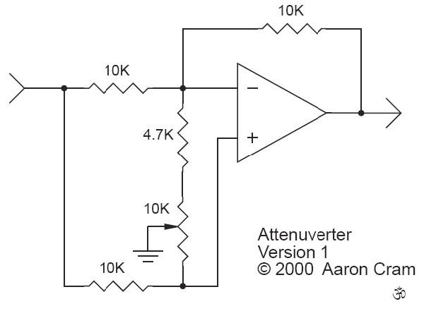
A search through the archives(gotta love this place) brought up a couple schematics, the most simple being this one:
http://www.buzzclick-music.com/inverter.jpg

Now on to the questions:
Does this circuit require any hidden power, that someone who isn`t a noob like me just assumes and knows?
What should the value of the resistor before the output be?
Is there any way I could use a 100k pot instead of 50k? I order these in large quantities since they are more commonly used in synths.
Does anyone have a PCB layout for something like this? I know Fonik has layouts for his attenuverting mixer and Buchlaesque voltage processor but that`s overkill for what I need.
If I decide not to go through with this, a dedicated attenuverter panel would be unnecessary since I would already have regular attenuators on every CV input, but I would have use for a few straight inverters. So what should I omit from that circuit to make it just two jacks, Input and Reverse Out?
In previous threads some stated that they don`t like this type of circuit because it cuts the control sweep in half and makes fine tuning too hard. I don`t know what kind of knobs and pots they were using, but do you think this would be a problem with 24mm pots and large MOTM style knobs? |
|
|
Back to top
|
|
 |
fonik

Joined: Jun 07, 2006
Posts: 3950
Location: Germany
Audio files: 23
|
|
|
Back to top
|
|
|
Funky40
Joined: Sep 24, 2005
Posts: 875
Location: Swiss
Audio files: 1
G2 patch files: 5
|
|
|
Back to top
|
|
|
frijitz
Joined: May 04, 2007
Posts: 1734
Location: NM USA
Audio files: 54
|
| Posted: Tue Nov 20, 2007 6:05 pm Post subject:
|
|
|
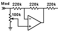
Good grief, why are these all so complicated? The one given here:
http://electro-music.com/forum/topic-21851.html
(the modulation input circuit at the bottom) works fine.
Oh well, I just lost an argument with a guy who said he wanted a simple circuit and ended up using something three times as complicated as my design.
Go figure. 

Ian |
|
|
Back to top
|
|
|
Scott Stites
Janitor


Joined: Dec 23, 2005
Posts: 4127
Location: Mount Hope, KS USA
Audio files: 96
|
| Posted: Tue Nov 20, 2007 6:15 pm Post subject:
|
|
|
Don't think I didn't spot that one, Ian  . .
I've been using that general design for years, though with different values. Rene Schmitz showed it to me; that one used a 1M pot and (IIRC 10K resistors(?). I used that for the longest time, then found that it didn't fully attenuate hard edged signals (at least that's what my scope told me). I then went to a 10K pot and I forget which resistor value, which got rid of the spikes, but I lost decent input impedance, so I killed the simplicity by buffering it with a 100K resistor/voltage follower. Thanks for sharing this - those values will get me back to the simplicity!
Cheers,
Scott
_________________
My Site |
|
|
Back to top
|
|
|
neandrewthal
Joined: May 11, 2007
Posts: 672
Location: Canada
|
| Posted: Tue Nov 20, 2007 6:38 pm Post subject:
|
|
|
| Thanks a bunch guys, I'll definitely have to try those out when I get my order of op-amps in. About the power, which pin gets the + and which gets the -? Also, can I daisy chain the power from whatever module I'm using this with or do I need to run a new line from the distro board? |
|
|
Back to top
|
|
|
fonik
Joined: Jun 07, 2006
Posts: 3950
Location: Germany
Audio files: 23
|
| Posted: Tue Nov 20, 2007 11:40 pm Post subject:
|
|
|
you are right, ian. and that's actually the method i used for the attenuverting mixer  . i just added a trimmer for calibration... . i just added a trimmer for calibration...
_________________

cheers,
matthias
____________
Big Boss at fonitronik
Tech Buddy at Random*Source |
|
|
Back to top
|
|
|
frijitz
Joined: May 04, 2007
Posts: 1734
Location: NM USA
Audio files: 54
|
| Posted: Wed Nov 21, 2007 5:52 am Post subject:
|
|
|
| fonik wrote: | | you are right, ian. and that's actually the method i used for the attenuverting mixer . i just added a trimmer for calibration... |
Right, I noticed that. And sure, if you use a center detent pot you may want a trimmer. But most of the time if you want zero you can just unplug the input.
Ian |
|
|
Back to top
|
|
|
v-un-v
Janitor

Joined: May 16, 2005
Posts: 8933
Location: Birmingham, England, UK
Audio files: 11
G2 patch files: 1
|
|
|
Back to top
|
|
|
frijitz
Joined: May 04, 2007
Posts: 1734
Location: NM USA
Audio files: 54
|
| Posted: Wed Nov 21, 2007 7:03 am Post subject:
|
|
|
| v-un-v wrote: | | I really dislike embedded links- too many windows! |
OK, but you did it wrong. The 220k at the far right is part of the circuit being controlled and will be different for different applications.
Ian |
|
|
Back to top
|
|
|
fonik
Joined: Jun 07, 2006
Posts: 3950
Location: Germany
Audio files: 23
|
| Posted: Wed Nov 21, 2007 7:08 am Post subject:
|
|
|
| frijitz wrote: | | ...most of the time if you want zero you can just unplug the input. |
speaking words of wisdom.
i tried center detent pots and i don't like them. the center detent is not sharp enough IMO and it is not precise (at least the alps and the alphas ia had on hand). as soon as you touch it the resistance would change slightly. to prevent this diodes from/to the wiper would create an "voltage hole" which i found undesirable too.
_________________
cheers,
matthias
____________
Big Boss at fonitronik
Tech Buddy at Random*Source |
|
|
Back to top
|
|
|
v-un-v
Janitor
Joined: May 16, 2005
Posts: 8933
Location: Birmingham, England, UK
Audio files: 11
G2 patch files: 1
|
| Posted: Wed Nov 21, 2007 7:12 am Post subject:
|
|
|

Sorry Ian  It's not the first time I've fucked up either It's not the first time I've fucked up either
But hey, its all part of life's little learning process! 
_________________
ACHTUNG!
ALLES TURISTEN UND NONTEKNISCHEN LOOKENPEEPERS!
DAS KOMPUTERMASCHINE IST NICHT FÜR DER GEFINGERPOKEN UND MITTENGRABEN! ODERWISE IST EASY TO SCHNAPPEN DER SPRINGENWERK, BLOWENFUSEN UND POPPENCORKEN MIT SPITZENSPARKSEN.
IST NICHT FÜR GEWERKEN BEI DUMMKOPFEN. DER RUBBERNECKEN SIGHTSEEREN KEEPEN DAS COTTONPICKEN HÄNDER IN DAS POCKETS MUSS.
ZO RELAXEN UND WATSCHEN DER BLINKENLICHTEN. |
|
|
Back to top
|
|
|
frijitz
Joined: May 04, 2007
Posts: 1734
Location: NM USA
Audio files: 54
|
| Posted: Wed Nov 21, 2007 7:44 am Post subject:
|
|
|
v-
Not a big deal, especially since the drawing makes it look like they go together.
Ian |
|
|
Back to top
|
|
|
etaoin

Joined: Jun 30, 2005
Posts: 761
Location: Utrecht, NL
|
| Posted: Wed Nov 21, 2007 7:45 am Post subject:
|
|
|
| fonik wrote: | | i tried center detent pots and i don't like them. the center detent is not sharp enough IMO and it is not precise (at least the alps and the alphas ia had on hand). as soon as you touch it the resistance would change slightly. to prevent this diodes from/to the wiper would create an "voltage hole" which i found undesirable too. |
Have you tried centre tapped pots? Even if you don't use the tap, the tap itself is a small area with no resistance, so once it's on the tap it won't change with small amounts of movement.
_________________
http://www.casia.org/modular/ |
|
|
Back to top
|
|
|
fonik
Joined: Jun 07, 2006
Posts: 3950
Location: Germany
Audio files: 23
|
| Posted: Wed Nov 21, 2007 8:01 am Post subject:
|
|
|
| Etaoin wrote: | | fonik wrote: | | i tried center detent pots and i don't like them. the center detent is not sharp enough IMO and it is not precise (at least the alps and the alphas ia had on hand). as soon as you touch it the resistance would change slightly. to prevent this diodes from/to the wiper would create an "voltage hole" which i found undesirable too. |
Have you tried centre tapped pots? Even if you don't use the tap, the tap itself is a small area with no resistance, so once it's on the tap it won't change with small amounts of movement. |
do you know a good source for center tapped alphas? i would give them a try.
_________________
cheers,
matthias
____________
Big Boss at fonitronik
Tech Buddy at Random*Source |
|
|
Back to top
|
|
|
etaoin
Joined: Jun 30, 2005
Posts: 761
Location: Utrecht, NL
|
| Posted: Wed Nov 21, 2007 8:03 am Post subject:
|
|
|
I got a few from either someone on this forum or on the sdiy list a while ago. He ordered a huge amount directly from Alpha. I paid $0.80 per pot I think. I'll need to check whom I got them from.
[edit] mailed you
_________________
http://www.casia.org/modular/ |
|
|
Back to top
|
|
|
etaoin
Joined: Jun 30, 2005
Posts: 761
Location: Utrecht, NL
|
| Posted: Wed Nov 21, 2007 1:04 pm Post subject:
|
|
|
On closer inspection the Alpha tapped ones I have don't seem to have the carbon-less mid-pot section I've seen on other pots.
_________________
http://www.casia.org/modular/ |
|
|
Back to top
|
|
|
Tim Servo

Joined: Jul 16, 2006
Posts: 924
Location: Silicon Valley
Audio files: 11
|
Posted: Wed Nov 21, 2007 6:02 pm Post subject:
Subject description: Center tapped pots |
|
|
| Etaoin wrote: | I got a few from either someone on this forum or on the sdiy list a while ago. He ordered a huge amount directly from Alpha. I paid $0.80 per pot I think. I'll need to check whom I got them from.
[edit] mailed you |
I'm pretty sure that was Tom Arnold on the SDIY list
xyzzy | at | sysabend | dot | org
He had a bunch of 50k center-tapped alphas that he special ordered. Dunno if he still has some, but he ordered a whole buncha buncha of them so it might be worth giving him a shout. I bought 20 or so myself, but I've yet to use them
Tim (they're #437 on the 'DIY to-do list') Servo
[Edit Blue Hell - changed the e-mail addie to be somewhat less obvious for bots] |
|
|
Back to top
|
|
|
fonik
Joined: Jun 07, 2006
Posts: 3950
Location: Germany
Audio files: 23
|
| Posted: Wed Nov 21, 2007 11:51 pm Post subject:
|
|
|
| Etaoin wrote: | | On closer inspection the Alpha tapped ones I have don't seem to have the carbon-less mid-pot section I've seen on other pots. |
thank, etaoin. i will give them a try nevertheless.
_________________
cheers,
matthias
____________
Big Boss at fonitronik
Tech Buddy at Random*Source |
|
|
Back to top
|
|
|
etaoin
Joined: Jun 30, 2005
Posts: 761
Location: Utrecht, NL
|
Posted: Thu Nov 22, 2007 12:09 am Post subject:
Subject description: Center tapped pots |
|
|
| Quote: | | I bought 20 or so myself, but I've yet to use them |
Which sounds awfully familiar...
Tim (they're #437 on the 'DIY to-do list') Servo
_________________
http://www.casia.org/modular/ |
|
|
Back to top
|
|
|
etaoin
Joined: Jun 30, 2005
Posts: 761
Location: Utrecht, NL
|
| Posted: Thu Nov 22, 2007 12:47 am Post subject:
|
|
|
| fonik wrote: | | thank, etaoin. i will give them a try nevertheless. |
If he still has them but you want to try one before you order a whole bunch of them, I will send you one.
_________________
http://www.casia.org/modular/ |
|
|
Back to top
|
|
|
loopcycle

Joined: Nov 06, 2006
Posts: 101
Location: California
|
| Posted: Sat Jul 02, 2011 9:53 pm Post subject:
|
|
|
| thanks for this conversation, bump for super useful info |
|
|
Back to top
|
|
|
mickey76
Joined: Jul 20, 2011
Posts: 5
Location: Belgium
|
| Posted: Fri Aug 26, 2011 4:00 pm Post subject:
|
|
|
What am I missing here guys?
Why not just use a pot to ground to attenuate a cv in?
Why would one prefer the type of circuit proposed here? |
|
|
Back to top
|
|
|
Dave Kendall

Joined: May 26, 2007
Posts: 421
Location: England
Audio files: 3
|
| Posted: Fri Aug 26, 2011 4:58 pm Post subject:
|
|
|
Mickey76 - with an attenuverter, you can have negative values of the CV as well as positive, depending on which way you turn the knob. In the centre you get zero.
cheers,
Dave
_________________
"Everything in moderation, including moderation" |
|
|
Back to top
|
|
|
mickey76
Joined: Jul 20, 2011
Posts: 5
Location: Belgium
|
| Posted: Fri Aug 26, 2011 5:45 pm Post subject:
|
|
|
| thanks! |
|
|
Back to top
|
|
|
|

 Forum index » DIY Hardware and Software