| Author |
Message |
bachus

Joined: Feb 29, 2004
Posts: 2922
Location: Up in that tree over there.
Audio files: 5
|
 Posted: Fri Mar 05, 2004 8:54 pm Post subject:
DIY DAW Posted: Fri Mar 05, 2004 8:54 pm Post subject:
DIY DAW |
  |
|
The purpose of this thread is to detail the DIY construction of a complete PC DAW that will provide capabilities and performance hardly distinguishable from a professional system. The software we will be running is Sonar 3 under MS Windows 2000. You could probably substitute XP without significant difficulty. We will document and report in this thread more or less as the project progresses so you can experience our hopes and fears, our tragedies and triumphs just like on reality TV. This will also prepare you to expect the kind difficulties one is likely to encounter in such an undertaking. I should note that I am not a hardware guru but I have both built and upgraded systems in years past. If anyone sees me in error or about to be, speak up!
If you are the kind of person who just has to get their hands on the "stuff" before they read the manual, or if you are the type who feels a vague sense of unease when they take screwdriver in hand, forget this and go find another thread quick!
The indispensable tool for such a project is a functioning computer with a connection to the Internet. You will inevitably come to places where you have no idea how to proceed and where the answer can only be found on the Internet. A good reference book is also recommended, in particular, "PC Hardware in a Nutshell," 3rd Edition, to which I will refer the reader on a number of occasions.
If you have no experience in this sort of thing you are advised to avoid making substitutions in the selected hardware, or altering the assembly procedure. You should also read to the end of this thread before you begin your own DAW to make certain that no compatibility problems were uncovered in the assembly/software-installation process.
A list of the selected hardware follows with a description of the motivation for each selection.
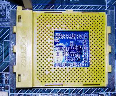
========== CPU: Athlon Barton core 3000+ 400 MHz FSB
Athlon because there is a little more bang per buck. Also because the only reason CPUs are as cheap and as rapidly evolving as they are is that IBM has competition. Without AMD we would all be much worse off.
NOTE : AMD makes an Athlon Barton core 3000+ that has a max FSB speed of 333 MHz. Don't get that one.
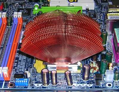
========== CPU Cooler: Zalman CNPS6000-Cu
Quiet or completely silent, depending--details later. One of the side goals here is to build a machine that is very quiet.
========== CPU / CPU Cooler thermal compound: ArcticSilver Ceramique
Do NOT use the more expensive stuff, either ArcticSilver's or anyone else's. They simply don't work as well.
Since I wrote this I have found a more methodical set of tests performed with better controls. It indicates that Arctic Silver Ceramique under performs (the more expensive) Arctic Silver 3 by 1/2 a degree Celsius. It also shows a product unfamiliar to me Shin-Etsu G-751 to perform significantly better than any other compound. If you can get it I would definitely use that. Though it may seem insignificant the thermal compound between your chip and chip cooler is a critical element of your system.
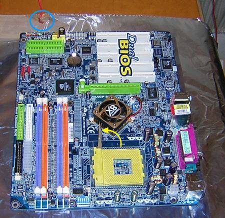
========== Mother Board: GIGABYTE GA-7N400-Pro2
Gigabyte is a reliable maker of stable motherboards. My personal preference is for ASUS but they don't make one that has all the features I required, which follow:
400 MHz FSB
Serial ATA (SATA) 150 RAID HD IO (explained later)
Supports up to 8 ATA devices. (Has ATA RAID as well though that will not be used.)
4 DIMMs DDR memory sockets allowing 2 GIG of ram in four 512 meg DIMMs. (As a DAW 1 gig is probably enough but I have other apps that will run on this machine that will benefit from 2).
Uses nVidia nForce2 ultra chipset--very stable.
Has onboard USB2, Firewire and gigabit ether net.
========== Memory: 1 gig, (two) Crucial brand DDR3200 CAS 3, 512 meg
You could go with Kingston memory and or memory with a lower CAS value. But don't buy the cheap stuff.
========== C: Drive: Seagate ATA Barracuda 120 gigs 8 meg buffer.
The Seagate Barracuda's reliable and significantly quieter that any other. Do NOT get the 2 Meg buffer version of this disc.
========== RAID: Drives: (two) Seagate SATA Barracuda 120 gigs 8 Meg buffer.
We will use these two drives in RAID 0 configuration for increased through-put (for more simultaneous tracks).
========== CD/DVD: Sony DRU-510AK DVD-CD +-RW
Gets good reviews and has all the formats except DVD data.
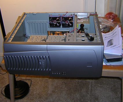
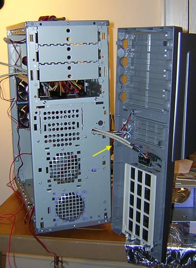
========== Case: Antec PLUS1080AMG
Contains high quality 430 wt power supply.
Has front and rear USB and Firewire ports.
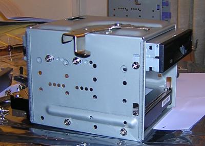
Has HD carriers that make installing and removing HDs a breeze.
========== Floppy: Sony
Samsung would do as well.
========== Video card: GeForce MX4000
The bottom of the line for a DAW. We're installing this card in the test setup but another will be used in our personal system. The video end of things will be discused in more detail later.
========== Audio / MIDI IO and Control surface: Tascam FW-1884 info here
There are better, but this is the best within my budget.
========== Approximate costs:
Computer parts: $1260.00 (newegg.com)
Tascam FW-1884: $1300.00 (musiciansfriend.com)
Win 2000 $140.00 (newegg.com)
Sonar 3 $300.00 (musiciansfriend.com)
shipping on all items 2/3 day service $100.00
total about $3110.00 (LESS VIDEO DISPLAY!)
========================================
With all the required parts in hand, plus
a set of screwdrivers,
a set of nut drivers,
91% Isopropyl alcohol,
4 or 5 very clean coffee filters,
a clean plastic baggie,
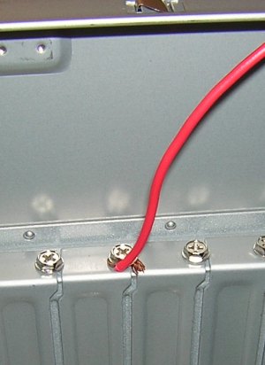
a length of wire and
an optional wrist-grounding strap
we are ready to begin.
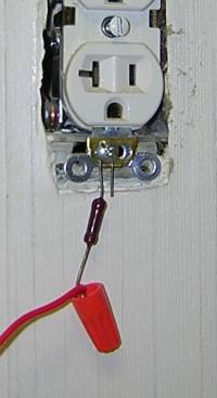
Oh, you'll also need a 1 meg ohm resistor,
some aluminum foil and a small wire nut.
====================================
Next: assembly.
| Description: |
|
| Filesize: |
31.61 KB |
| Viewed: |
24473 Time(s) |
|
Last edited by bachus on Mon Mar 08, 2004 9:19 am; edited 3 times in total |
|
|
Back to top
|
|
 |
mosc
Site Admin

Joined: Jan 31, 2003
Posts: 18198
Location: Durham, NC
Audio files: 213
G2 patch files: 60
|
| Posted: Fri Mar 05, 2004 9:26 pm Post subject:
|
|
|
Thanks for posting this. Interesting. I edited your post because you had a really long URL pointing to the Tascam Control Surface information. I just used the [URL= feature. Hope you don't mind. 
Great that you are running RAID 0 which is striping for increased speed. Why don't you go with RAID 1/0 which adds redundant disks as well? Sure you'll have 4 disks instead of 2, but your get redundancy which can prevent much heartache. I'm running a system like that and sleep better at night knowing I can have a disk failure without losing any data.
Good move on the Zalman CPU cooler. The CPU cooler is usually the major source of noise in a computer system. |
|
|
Back to top
|
|
|
mosc
Site Admin
Joined: Jan 31, 2003
Posts: 18198
Location: Durham, NC
Audio files: 213
G2 patch files: 60
|
| Posted: Fri Mar 05, 2004 9:34 pm Post subject:
|
|
|
If you want high-performance systems like this and don't want to go the DIY route, consider Clever Bison Computers. This is run by Daniel, one of our members. He builds all of my systems. He'll customize your computer so you'll get exactly what you need and nothing you don't.
Also, if anyone is going to be buying any musical equipment, please go to Musician's Friend via the link on our front page. They will help pay our bills via their affiliate program, but you must click through from the front page. (Sorry for the shameless plug). |
|
|
Back to top
|
|
|
Cyxeris

Joined: Oct 30, 2003
Posts: 1125
Location: Louisville, KY
|
| Posted: Fri Mar 05, 2004 9:56 pm Post subject:
|
|
|
Not a plug. A strategic alliance!
_________________
∆ Cyx ∆
"Yeah right, who's the only one here who knows secret illegal ninja moves from the government?"
-Napoleon Dynamite |
|
|
Back to top
|
|
|
bachus
Joined: Feb 29, 2004
Posts: 2922
Location: Up in that tree over there.
Audio files: 5
|
| Posted: Sat Mar 06, 2004 4:20 am Post subject:
|
|
|
| mosc wrote: | | Thanks for posting this. Interesting. I edited your post because you had a really long URL pointing to the Tascam Control Surface information. I just used the [URL= feature. Hope you don't mind. |
No, thanks, just ignorance on my part.
| mosc wrote: | | Great that you are running RAID 0 which is striping for increased speed. Why don't you go with RAID 1/0 which adds redundant disks as well? Sure you'll have 4 disks instead of 2, but your get redundancy which can prevent much heartache. I'm running a system like that and sleep better at night knowing I can have a disk failure without losing any data. |
Gees! Is THAT why I've been having trouble sleeping?!  The SATA RAID controller on this MB only supports 0/1 not 0/1/0+1. I agree that the lack of redundancy is an important issue as in mode 0 (striping only) you have twice the chance of HD failure. As far as I know, no MB currently supports SATA 0+1, so a controller card would be required, and you could add that to this system later. An alternative would be to go with the GA-7N400-L or similar MB (save ~$30) and put that towards the desired controller. The SATA RAID controller on this MB only supports 0/1 not 0/1/0+1. I agree that the lack of redundancy is an important issue as in mode 0 (striping only) you have twice the chance of HD failure. As far as I know, no MB currently supports SATA 0+1, so a controller card would be required, and you could add that to this system later. An alternative would be to go with the GA-7N400-L or similar MB (save ~$30) and put that towards the desired controller.
The GA-7N400-Pro2's IDE port supports RAID 0+1 (mirroring and striping) which would be just fine for audio and may be a better alternative for some. But I also play with Maya and video and felt the extra performance of SATA was worth the hassle of additional backup precautions. I'm planning to add another HD for that purpose but haven't decided on the details of that as yet.
| mosc wrote: | | Good move on the Zalman CPU cooler. The CPU cooler is usually the major source of noise in a computer system. |
And as long as you brought it up now I will mention that the Zalman cooler is the first step in reducing system noise. Once the system is completed I'll get out my dB meter and make some decisions as to what all needs to be done. Replacing the Antec case fans with low noise models is definitely in the works and there are additional steps that might be taken as well. |
|
|
Back to top
|
|
|
bachus
Joined: Feb 29, 2004
Posts: 2922
Location: Up in that tree over there.
Audio files: 5
|
|
|
Back to top
|
|
|
bachus
Joined: Feb 29, 2004
Posts: 2922
Location: Up in that tree over there.
Audio files: 5
|
|
|
Back to top
|
|
|
bachus
Joined: Feb 29, 2004
Posts: 2922
Location: Up in that tree over there.
Audio files: 5
|
|
|
Back to top
|
|
|
bachus
Joined: Feb 29, 2004
Posts: 2922
Location: Up in that tree over there.
Audio files: 5
|
|
|
Back to top
|
|
|
mosc
Site Admin
Joined: Jan 31, 2003
Posts: 18198
Location: Durham, NC
Audio files: 213
G2 patch files: 60
|
| Posted: Sun Mar 07, 2004 9:35 pm Post subject:
|
|
|
| Wow, that's one of the most colorfull mother boards I've ever seen! |
|
|
Back to top
|
|
|
Cyxeris
Joined: Oct 30, 2003
Posts: 1125
Location: Louisville, KY
|
| Posted: Sun Mar 07, 2004 10:33 pm Post subject:
|
|
|
Poseidon, check the cooler on the chipset. My goodness...
_________________
∆ Cyx ∆
"Yeah right, who's the only one here who knows secret illegal ninja moves from the government?"
-Napoleon Dynamite |
|
|
Back to top
|
|
|
bachus
Joined: Feb 29, 2004
Posts: 2922
Location: Up in that tree over there.
Audio files: 5
|
| Posted: Mon Mar 08, 2004 5:10 am Post subject:
|
|
|
| mosc wrote: | | Wow, that's one of the most colorfull mother boards I've ever seen! |
Thank goodness the case doesn't have one of those see through doors. 
| Cyxeris wrote: | | Poseidon, check the cooler on the chipset. My goodness... |
Yea, that's kind of a sore point. I swore that I would never buy another MB with a fan on the chipset after I had to replace the one on my current machine--just another mechanical thing to fail. Gees what a guy will do to get four DIMM sockets! I hope it's noisy. That'll give me an excuse to replace it with an adequate passive heat sink. I can't tell at this point, the case fans are so loud. Got a dozen low noise fans on order. |
|
|
Back to top
|
|
|
bachus
Joined: Feb 29, 2004
Posts: 2922
Location: Up in that tree over there.
Audio files: 5
|
|
|
Back to top
|
|
|
bachus
Joined: Feb 29, 2004
Posts: 2922
Location: Up in that tree over there.
Audio files: 5
|
|
|
Back to top
|
|
|
bachus
Joined: Feb 29, 2004
Posts: 2922
Location: Up in that tree over there.
Audio files: 5
|
| Posted: Thu Mar 11, 2004 7:46 am Post subject:
|
|
|
| Alas I failed at anything like real-time reporting. The machine has been minimally functional for nearly a week. But newegg.com shipped 4 ATAs instead of 2 ATA and 2 SATA hard drives. The SATAs are now in hand and when time permits my part of the thread will resume. In any case, from past experience, if this is the worst difficulty one should be happy. |
|
|
Back to top
|
|
|
bachus
Joined: Feb 29, 2004
Posts: 2922
Location: Up in that tree over there.
Audio files: 5
|
|
|
Back to top
|
|
|
bachus
Joined: Feb 29, 2004
Posts: 2922
Location: Up in that tree over there.
Audio files: 5
|
|
|
Back to top
|
|
|
bachus
Joined: Feb 29, 2004
Posts: 2922
Location: Up in that tree over there.
Audio files: 5
|
|
|
Back to top
|
|
|
bachus
Joined: Feb 29, 2004
Posts: 2922
Location: Up in that tree over there.
Audio files: 5
|
|
|
Back to top
|
|
|
mosc
Site Admin
Joined: Jan 31, 2003
Posts: 18198
Location: Durham, NC
Audio files: 213
G2 patch files: 60
|
| Posted: Wed Mar 24, 2004 8:23 am Post subject:
|
|
|
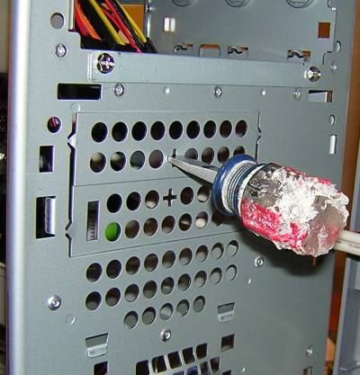
Hmm... Looks like a pretty involved process.
But about this screwdriver. Do have a dog, or have you been nervous lately?  
|
|
|
Back to top
|
|
|
bachus
Joined: Feb 29, 2004
Posts: 2922
Location: Up in that tree over there.
Audio files: 5
|
|
|
Back to top
|
|
|
bachus
Joined: Feb 29, 2004
Posts: 2922
Location: Up in that tree over there.
Audio files: 5
|
| Posted: Sun Jul 18, 2004 5:56 pm Post subject:
|
|
|
I need to post the following warning:
I have been running the studio full out (all 4 machines fully cranked) only recently and have to report that the ZALMAN CNPS6000 heatsink/fan has been inadequate on one of the Athlon 3000s. Because it's OK on another identical machine I remounted it, but with no significant improvement. So I'm going to upgrade both the Athlon Barton 3000 machines to ZALMAN CNPS7000A-Cu sink/fans. The two other machines use Athlon Barton 2100 and 2800 CPUs and run perfectly cool with CNPS6000s. |
|
|
Back to top
|
|
|
mosc
Site Admin
Joined: Jan 31, 2003
Posts: 18198
Location: Durham, NC
Audio files: 213
G2 patch files: 60
|
| Posted: Sun Jul 18, 2004 6:05 pm Post subject:
|
|
|
| Sorry the Zalman didn't work out for you. Daniel has heard that from other people as well. Can't wait to hear you music. |
|
|
Back to top
|
|
|
|

 Forum index » How-tos

 LAN. (As I told electro80, my karma failed that test!). Problems with the LAN have been the cause of the extended delay in my work on this thread. BTW I am at present loading VSL onto the second DIY machine.