| Author |
Message |
talkboxert
Joined: Oct 08, 2008
Posts: 16
Location: Amsterdam, Netherlands
|
|
|
Back to top
|
|
 |
Luka

Joined: Jun 29, 2007
Posts: 1003
Location: Melb.
|
 Posted: Fri Nov 28, 2008 12:33 am Post subject: Posted: Fri Nov 28, 2008 12:33 am Post subject:
|
  |
|
it says 47n on the schematic so id go with that
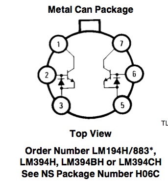
lm394 is ok and pin 1 (should have a dot on this corner) should be in the top left corner according of each bc547 pair
check out the datasheet if you need any more info
just google lm394 datasheet
if you look at the bc547 you will notice the lm394 is just 2 transistors and you can match the collectors/emiiters up with the board pattern
_________________
problemchild
melbourne australia
http://cycleofproblems.blogspot.com/
http://www.last.fm/user/prblmchild |
|
|
Back to top
|
|
|
yusynth

Joined: Nov 24, 2005
Posts: 1314
Location: France
|
| Posted: Fri Nov 28, 2008 1:49 am Post subject:
|
|
|
Question 1:
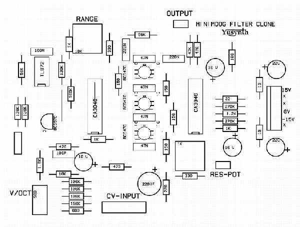
both 22nF and 47nF are correct but I have found that I got a faithfuller minimoog sounding using 47nF, therefore I'd suggest that you go for the 47nF caps.
Question 2:
Yes the LM394 are there provided as substitute for the SSM2210 which are already substitue for the BC547s.
See below the layout diagram
| Description: |
|
| Filesize: |
46.03 KB |
| Viewed: |
24287 Time(s) |
|
| Description: |
|
| Filesize: |
319.76 KB |
| Viewed: |
363 Time(s) |
| This image has been reduced to fit the page. Click on it to enlarge. |
|
_________________
Yves |
|
|
Back to top
|
|
|
talkboxert
Joined: Oct 08, 2008
Posts: 16
Location: Amsterdam, Netherlands
|
| Posted: Fri Nov 28, 2008 1:04 pm Post subject:
|
|
|
Can't be any clearer...... |
|
|
Back to top
|
|
|
talkboxert
Joined: Oct 08, 2008
Posts: 16
Location: Amsterdam, Netherlands
|
|
|
Back to top
|
|
|
yusynth
Joined: Nov 24, 2005
Posts: 1314
Location: France
|
| Posted: Sat Nov 29, 2008 8:03 am Post subject:
|
|
|
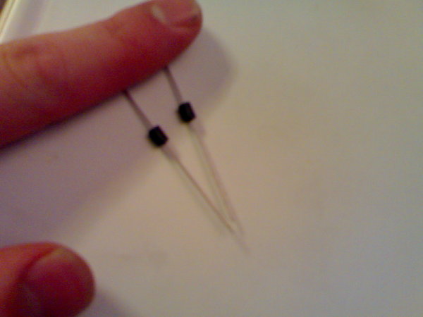
Hi
These are inductors (a wire wound around a ferrite bead), they are provided as substitutes for the two 10 ohm resistors (R1 R2), if you check on bridechamber's site you'll see it mentioned : | Quote: | | R1 and R2 are replaced with ferrite beads. |
Cheers
Yves
_________________
Yves |
|
|
Back to top
|
|
|
talkboxert
Joined: Oct 08, 2008
Posts: 16
Location: Amsterdam, Netherlands
|
| Posted: Sat Nov 29, 2008 8:18 am Post subject:
thankx |
|
|
| thanks again! |
|
|
Back to top
|
|
|
LetterBeacon
Joined: Mar 18, 2008
Posts: 454
Location: London, UK
|
| Posted: Sat Nov 29, 2008 9:23 am Post subject:
|
|
|
I'm hoping to build this soon, and so I'm just collecting the components together. You specify the 47nf caps to be matched to 1% - are these appropriate capacitors?
Also, on the wiring diagram it looks like the resistors all have 5% tolerance. Is that correct, or should I use ones with 1% tolerance?
Thanks a lot. |
|
|
Back to top
|
|
|
yusynth
Joined: Nov 24, 2005
Posts: 1314
Location: France
|
| Posted: Sat Nov 29, 2008 10:57 am Post subject:
|
|
|
| LetterBeacon wrote: | | I'm hoping to build this soon, and so I'm just collecting the components together. You specify the 47nf caps to be matched to 1% - are these appropriate capacitors? |
These caps are OK. When I say 1%, this means that you take a batch of 47nF caps and you measure them with a capacimeter, then you select those within 1%. What counts is not the accuracy with respect to 47nF but rather the closeness between the values : they don't need to be 47nF exactly , but the four caps must have the same value within 1%, that is, it can be four caps with a value of 44nF fo example.
| LetterBeacon wrote: | Also, on the wiring diagram it looks like the resistors all have 5% tolerance. Is that correct, or should I use ones with 1% tolerance?
Thanks a lot. |
5% is OK.
_________________
Yves |
|
|
Back to top
|
|
|
LetterBeacon
Joined: Mar 18, 2008
Posts: 454
Location: London, UK
|
| Posted: Sat Nov 29, 2008 11:02 am Post subject:
|
|
|
| Great, thanks a lot! |
|
|
Back to top
|
|
|
talkboxert
Joined: Oct 08, 2008
Posts: 16
Location: Amsterdam, Netherlands
|
| Posted: Sun Nov 30, 2008 6:44 am Post subject:
Ferrite Beads |
|
|
| Quote: | | R1 and R2 are replaced with ferrite beads. |
Just out of interest, why is this?
Also to make it sound more close to the original?
Cheers |
|
|
Back to top
|
|
|
Funky40
Joined: Sep 24, 2005
Posts: 875
Location: Swiss
Audio files: 1
G2 patch files: 5
|
|
|
Back to top
|
|
|
LetterBeacon
Joined: Mar 18, 2008
Posts: 454
Location: London, UK
|
| Posted: Sun Nov 30, 2008 9:43 am Post subject:
|
|
|
Yves, just out of interest, what type of capacitor did you use in the circuit? I was going to use those polyester ones, but I've just read this:
| Harry Bissell wrote: | | For all frequency sensitive applications, film caps are the best choice. Polystyrene is the best, followed by polycarbonate, and polyester (Mylar). Mylar capacitors should always be avoided in Sample/Hold and VCO applications, and used with caution in VCF circuits. If the capacitance value is very small then mica or COG/NPO ceramics may be used. |
|
|
|
Back to top
|
|
|
yusynth
Joined: Nov 24, 2005
Posts: 1314
Location: France
|
| Posted: Sun Nov 30, 2008 10:19 am Post subject:
|
|
|
I use polyester film capacitors for the filter.
_________________
Yves |
|
|
Back to top
|
|
|
jbeuckm

Joined: Nov 30, 2008
Posts: 165
Location: Stockholm
Audio files: 9
|
Posted: Sat Dec 13, 2008 1:19 am Post subject:
Self-oscillation
Subject description: can't get it :( |
|
|
I have a working model built but can't achieve self oscillation even with the emphasis trimmer and pot all the way up. I have to admit that I did not know to match the 47n capacitors to each other when I picked them. Could mismatched capacitors cause weak emphasis? What else would prevent self-oscillation?
Thank you,
-joe |
|
|
Back to top
|
|
|
yusynth
Joined: Nov 24, 2005
Posts: 1314
Location: France
|
| Posted: Sat Dec 13, 2008 2:23 am Post subject:
|
|
|
No, I think it should oscillate even with mismatched ladder caps.
OK check all the solders, swap or change the CA3046s.
_________________
Yves |
|
|
Back to top
|
|
|
numbertalk

Joined: May 05, 2008
Posts: 992
Location: Austin, TX
Audio files: 5
|
| Posted: Sat Dec 13, 2008 7:49 am Post subject:
|
|
|
| What voltage power supply are you using? I first tried this with 2 9V batteries, before I had a bench or cabinet power supply, and I had the same problem. I think it really needs the 15V to oscillate. If you're using a 15VDC supply maybe it's a problem with one of the soldered connections to power on that chip. |
|
|
Back to top
|
|
|
jbeuckm
Joined: Nov 30, 2008
Posts: 165
Location: Stockholm
Audio files: 9
|
| Posted: Sat Dec 13, 2008 11:05 am Post subject:
|
|
|
| numbertalk wrote: | | What voltage power supply are you using? |
That was it! I thought I was using my 15v rack but it was 12v. It oscillates nicely on +/-15v. Nice filter. Thanks for the help. |
|
|
Back to top
|
|
|
LetterBeacon
Joined: Mar 18, 2008
Posts: 454
Location: London, UK
|
| Posted: Sun Jan 11, 2009 10:17 am Post subject:
|
|
|
I can't seem to find a source for the large 10K and 1K trim pots in the UK. Can anyone point me to where I can find these online?
Thanks! |
|
|
Back to top
|
|
|
yusynth
Joined: Nov 24, 2005
Posts: 1314
Location: France
|
|
|
Back to top
|
|
|
LetterBeacon
Joined: Mar 18, 2008
Posts: 454
Location: London, UK
|
| Posted: Sun Jan 11, 2009 10:42 am Post subject:
|
|
|
Thanks for that. I went to Maplin yesterday and bought what I thought were the ones you linked to, but it turns out I bought the smaller ones instead.  |
|
|
Back to top
|
|
|
furio

Joined: Dec 25, 2009
Posts: 117
Location: Austria
Audio files: 1
|
| Posted: Fri Nov 25, 2011 3:40 pm Post subject:
|
|
|
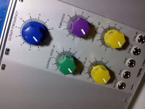
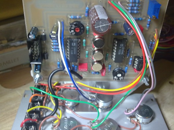
Tomorrow I try my new filter 
| Description: |
|
| Filesize: |
463.71 KB |
| Viewed: |
203 Time(s) |
| This image has been reduced to fit the page. Click on it to enlarge. |
|
| Description: |
|
| Filesize: |
507.26 KB |
| Viewed: |
230 Time(s) |
| This image has been reduced to fit the page. Click on it to enlarge. |
|
|
|
|
Back to top
|
|
|
|

 Forum index » DIY Hardware and Software » YuSynth