| Author |
Message |
gabbagabi

Joined: Nov 29, 2008
Posts: 652
Location: Berlin by n8
Audio files: 23
|
 Posted: Mon Dec 01, 2008 8:06 am Post subject:
Problem with the ADSR Posted: Mon Dec 01, 2008 8:06 am Post subject:
Problem with the ADSR
Subject description: no Out Signal |
  |
|
Ahoi,
I've been finished the ADSR.
I put a Pulse Signal on the Gate In - nothing on the Output.
Turning the Pots, makes no change.
But the 555 is heating.
Maybe somebody got a similar problem before, or an idea what i do wrong?
Last edited by gabbagabi on Mon Apr 14, 2014 3:02 am; edited 1 time in total |
|
|
Back to top
|
|
 |
yusynth

Joined: Nov 24, 2005
Posts: 1314
Location: France
|
| Posted: Mon Dec 01, 2008 12:50 pm Post subject:
|
|
|
If the 555 is hot this is not normal, this suggests that either there is an error somewhere in the value of a component or there is a solder bridge somewhere. A good thing to would be to measure voltages at some key points. For example what voltages do you get at the collector of the trannies with and without GATE signal (which is supposed to be at least 5V). What voltage do get at the pins of the 555 ?
_________________
Yves |
|
|
Back to top
|
|
|
gabbagabi
Joined: Nov 29, 2008
Posts: 652
Location: Berlin by n8
Audio files: 23
|
| Posted: Mon Dec 01, 2008 3:15 pm Post subject:
|
|
|
1. thank you! the ADSR is the first module of your Modules that dont work immediately.
this Time I use the YuSynth LFO for the Gate signal
With signal on gate in
Q1 0v ; 0,7v pulse
Q2 0v ; 0,9v pulse
Q3 static 0,9v
Q4 15V
Without
Q1 0,7vstatic
Q2 0v static
Q3 0,9vstatic
Q4 15Vstatic
555
1 0v
2 0,9v
3 0v
4 0,9v
5 0v
6 0,1v
7 15v
8 15v
Last edited by gabbagabi on Mon Apr 14, 2014 3:03 am; edited 1 time in total |
|
|
Back to top
|
|
|
yusynth
Joined: Nov 24, 2005
Posts: 1314
Location: France
|
| Posted: Tue Dec 02, 2008 1:09 am Post subject:
|
|
|
| g.gabba wrote: | | 1. thank you! the ADSR is the first module of your Modules that dont work immediately. |
Funny because this is the module I usually recommend beginners to start with because it is not a tricky one 
| g.gabba wrote: | this Time I use the YuSynth LFO for the Gate signal
With signal on gate in
Q1 0v ; 0,7v pulse
Q2 0v ; 0,9v pulse
Q3 static 0,9v
Q4 15V
Without
Q1 0,7vstatic
Q2 0v static
Q3 0,9vstatic
Q4 15Vstatic
|
Are these measured at the collector pin of the trannies ?
If so there is definitely a problem with the input stage, the voltages that are expected are
GATE OFF
Q1 collector : close to 15V
Q2 collector : 0V
Q3 collector : 0V
GATE ON
Q1 collector : 0V
Q2 collector : close to 15V
Q3 collector : a brief (10ms) pulse to 15V and return to 0V
| g.gabba wrote: |
I use the YuSynth LFO for the Gate signal
when i connect the lfo with the Gate in the LED on the LFO is dark
on the Gate in is now only a +/- 1,4 V pulse - may thats the problem
Unplugged the LFO Ampl is +/-4 V
So i amplify the signal with a mixer over 3v at the Gate in
--> nothing
any idea? |
OK what you say is that the input GATE level drops dramatically when it's plugged to the ADSR input. Obviously this is not normal, check the values of the input resistors (thes on the latest version are R4,R5,R6 (by the way R6 should be 22k, I must correct the schemo). Check also that D1, Q1,Q2,Q3 and Q4 are sane.
_________________
Yves |
|
|
Back to top
|
|
|
gabbagabi
Joined: Nov 29, 2008
Posts: 652
Location: Berlin by n8
Audio files: 23
|
| Posted: Wed Dec 03, 2008 5:08 am Post subject:
|
|
|
I measure the Q Voltages at the Collector.
Cant find some Difference between my Parts on the board and the List-Pic
thank you very much 4 your help.
gabbagabi
Last edited by gabbagabi on Mon Apr 14, 2014 3:00 am; edited 1 time in total |
|
|
Back to top
|
|
|
yusynth
Joined: Nov 24, 2005
Posts: 1314
Location: France
|
| Posted: Wed Dec 03, 2008 5:48 am Post subject:
|
|
|
| g.gabba wrote: | | I think, i teach 2 poor Copperboards the swiming in Salpeter Acid , drill some holes in and makes them nice warm whith the soldering iron . |
 Hu, I don't understand this sentence, can you rephrase it ? Hu, I don't understand this sentence, can you rephrase it ?
_________________
Yves |
|
|
Back to top
|
|
|
gabbagabi
Joined: Nov 29, 2008
Posts: 652
Location: Berlin by n8
Audio files: 23
|
| Posted: Wed Dec 03, 2008 6:26 am Post subject:
|
|
|
 ups sry ups sry
it means i make 2 new ADSR
Last edited by gabbagabi on Mon Apr 14, 2014 2:58 am; edited 1 time in total |
|
|
Back to top
|
|
|
yusynth
Joined: Nov 24, 2005
Posts: 1314
Location: France
|
| Posted: Wed Dec 03, 2008 6:59 am Post subject:
|
|
|
Thanks for the explanation
_________________
Yves |
|
|
Back to top
|
|
|
gabbagabi
Joined: Nov 29, 2008
Posts: 652
Location: Berlin by n8
Audio files: 23
|
| Posted: Wed Dec 03, 2008 10:27 am Post subject:
|
|
|
edit: i was wrong
Last edited by gabbagabi on Mon Apr 14, 2014 2:58 am; edited 1 time in total |
|
|
Back to top
|
|
|
gabbagabi
Joined: Nov 29, 2008
Posts: 652
Location: Berlin by n8
Audio files: 23
|
| Posted: Wed Dec 03, 2008 11:33 am Post subject:
|
|
|
edit: i was wrong
Last edited by gabbagabi on Mon Apr 14, 2014 3:04 am; edited 1 time in total |
|
|
Back to top
|
|
|
yusynth
Joined: Nov 24, 2005
Posts: 1314
Location: France
|
| Posted: Wed Dec 03, 2008 11:37 am Post subject:
|
|
|
You mean it auto-oscillates ?
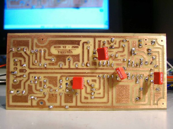
If so can you post detailed photo of your PCB (component side and track side)
_________________
Yves |
|
|
Back to top
|
|
|
gabbagabi
Joined: Nov 29, 2008
Posts: 652
Location: Berlin by n8
Audio files: 23
|
|
|
Back to top
|
|
|
gabbagabi
Joined: Nov 29, 2008
Posts: 652
Location: Berlin by n8
Audio files: 23
|
| Posted: Wed Dec 03, 2008 12:10 pm Post subject:
|
|
|
it auto osc. from the first moment - so i chang the caps
before i try it whith ceramic caps |
|
|
Back to top
|
|
|
gabbagabi
Joined: Nov 29, 2008
Posts: 652
Location: Berlin by n8
Audio files: 23
|
| Posted: Wed Dec 03, 2008 1:32 pm Post subject:
|
|
|
i disconnect all caps
still oscilating
i disconnect the elkos at the Power input
now its oscilating with a high frq
try to connect and disconnect the other caps
it restarts to reheating the 555
and it stops to work
Last edited by gabbagabi on Mon Apr 14, 2014 3:05 am; edited 1 time in total |
|
|
Back to top
|
|
|
yusynth
Joined: Nov 24, 2005
Posts: 1314
Location: France
|
| Posted: Wed Dec 03, 2008 2:10 pm Post subject:
|
|
|
| g.gabba wrote: | | ok. an osc cant osc without a cap |
No, but a circuit with a feedback loop can oscillate and if your module oscillates it's probably because such a loop exists...
_________________
Yves |
|
|
Back to top
|
|
|
yusynth
Joined: Nov 24, 2005
Posts: 1314
Location: France
|
| Posted: Wed Dec 03, 2008 2:22 pm Post subject:
|
|
|
How do you power up the circuit ? Are you using a linear power suplly ?
_________________
Yves |
|
|
Back to top
|
|
|
gabbagabi
Joined: Nov 29, 2008
Posts: 652
Location: Berlin by n8
Audio files: 23
|
| Posted: Thu Dec 04, 2008 1:31 am Post subject:
|
|
|
a linear
i forgot the loop, so i will focus also on a loop.
Last edited by gabbagabi on Mon Apr 14, 2014 3:06 am; edited 1 time in total |
|
|
Back to top
|
|
|
gabbagabi
Joined: Nov 29, 2008
Posts: 652
Location: Berlin by n8
Audio files: 23
|
| Posted: Thu Dec 04, 2008 11:22 am Post subject:
|
|
|
the negative supply voltage was connectet to the wrong place
thank you very much for your support
Last edited by gabbagabi on Mon Apr 14, 2014 2:55 am; edited 1 time in total |
|
|
Back to top
|
|
|
Ali M
Joined: Sep 01, 2009
Posts: 96
Location: uk
|
| Posted: Mon Oct 03, 2011 6:28 am Post subject:
|
|
|
| yusynth wrote: | Are these measured at the collector pin of the trannies ?
If so there is definitely a problem with the input stage, the voltages that are expected are
GATE OFF
Q1 collector : close to 15V
Q2 collector : 0V
Q3 collector : 0V
GATE ON
Q1 collector : 0V
Q2 collector : close to 15V
Q3 collector : a brief (10ms) pulse to 15V and return to 0V
|
Hi Yves, digging up an old thread.
My adsr isn't working I am not getting 15v on Q1 collector during GATE OFF. I am trying to trigger it with a push button. I have tried a sig gen but it didn't make any difference.
All my IC's are getting the right voltage, and I have checked my power supply polarity.
I have got others to build so I might try them to see if they work then compare the two circuits. Any help would be much appreciated.
Cheers
Ali |
|
|
Back to top
|
|
|
yusynth
Joined: Nov 24, 2005
Posts: 1314
Location: France
|
| Posted: Wed Oct 05, 2011 1:06 am Post subject:
|
|
|
Hi Ali
Which version of the ADSR have you built ?
Can you simply check with a voltmeter what voltage you get on the basis of Q1 with and without pushing the button ?
It should be 0V without and something like 0.7V to 1.0V when pushing.
_________________
Yves |
|
|
Back to top
|
|
|
Ali M
Joined: Sep 01, 2009
Posts: 96
Location: uk
|
| Posted: Wed Oct 05, 2011 2:35 am Post subject:
|
|
|
Yves, i am getting some really weird errors with my circuit now. I found what may have been a short and since then the whole circuit is acting very strangly. I am getting 12v on the Vcc of my Op-amp and no voltage to any of the transistors.
I tried the other adsr I had built and that doesn't work either, the LED is premenantly on 
But I will focus on the first one, I was just hoping it would work straight away so I could compare voltages and swap ic's etc...
I have built the old version, and I etched my own boards. Maybe not the best idea, but there are no shorts and the continuity is good. Most circuits I build work, its rare that 2 of the same thing don't work.
I suspected the IC's, until the circuit was giving stange voltages now I feel it could be any number of things.
I am going to replace some components and give try and get it out of its sorry state today. I will report back asap. |
|
|
Back to top
|
|
|
yusynth
Joined: Nov 24, 2005
Posts: 1314
Location: France
|
| Posted: Wed Oct 05, 2011 4:47 am Post subject:
|
|
|
Can you post some photos of your PCB : component side view and track view.
_________________
Yves |
|
|
Back to top
|
|
|
Ali M
Joined: Sep 01, 2009
Posts: 96
Location: uk
|
| Posted: Wed Oct 05, 2011 6:24 am Post subject:
|
|
|
I tried taking pictures of the circuit but they really don't come out very well....
I swapped the 10 ohm resistors. Now I am getting an output.
The LED is lighting in responce to the settings of the front panel pots.
But the image on the scope seems to be either HIGH, gate on or LOW gate off. It doesn't seem to react to the front panel settings.
Q1
C = 0.7
B = 0
E = 0
Q2
C = 0
B = 0.7
E = 0
Q3
C = 11.2
B = 0.5
E = 0
When I push the trigger the voltages all go to '0' apart from Q3 collector, which stays at 11.2.
I think I am getting there. Will try to upload some pics with a better camera. |
|
|
Back to top
|
|
|
Ali M
Joined: Sep 01, 2009
Posts: 96
Location: uk
|
| Posted: Fri Oct 07, 2011 5:40 am Post subject:
|
|
|
Sorted now,
I few of the resistors were not working. Now I am getting a nice smooth envelopes on the scope. I haven't got a CV midi convertor yet, to test the input.
And I am still a little concerned that I am not getting correct voltages to Q1 - Q3. But I have something going now and should be able to find my own way with it.
The other circuit that had the LED permenantly ON was a dodgy transistor, but I haven't got that one working yet, but It shouldn't be too tough.
Have learnt a great deal by doing this circuit. And I have never had so many components fail on the same board before, it must have been a short!
Thanks Yves, now I have to sort out that VCO! |
|
|
Back to top
|
|
|
|

 Forum index » DIY Hardware and Software » YuSynth