| What "chipset" would you like to see in a Dim D PCB |
| Original chips. They are still out there. |
|
76% |
[ 39 ] |
| Low voltage BBDs - easier to get, probably more noisy. Takes longer to design. |
|
5% |
[ 3 ] |
| Make a PCB that allows both options. Will be more expensive (more PCB area required!), and will take the longest to design. |
|
13% |
[ 7 ] |
| Not interested. (Who needs a Dim D? And isn't there another Dim D project on the way?!) |
|
3% |
[ 2 ] |
|
| Total Votes : 51 |
|
| Author |
Message |
jhaible

Joined: May 25, 2007
Posts: 2014
Location: Germany
Audio files: 24
|
 Posted: Fri Jan 09, 2009 12:17 pm Post subject: Posted: Fri Jan 09, 2009 12:17 pm Post subject:
|
  |
|
| whomper wrote: |
Right, I have not encountered such an enclosure yet  |
Neither have I, before, if that is a comfort to you.
8-pin SIL, yes - but 8-pin with one pin missing, making it a 6 + 1, 7-pin - no.
But it's a clever solution - it prevents soldering in backwards.
JH.
_________________
"I tell you the truth, if anyone says to this mountain, 'Go, throw yourself into the sea,' and does not doubt in his heart but believes that what he says will happen, it will be done for him. Therefore I tell you, whatever you ask for in prayer, believe that you have received it, and it will be yours." (Mk 11,23f) |
|
|
Back to top
|
|
 |
etaoin

Joined: Jun 30, 2005
Posts: 761
Location: Utrecht, NL
|
| Posted: Sat Jan 10, 2009 6:19 am Post subject:
|
|
|
With the HA1457s I used the pin isn't missing, it's actually cut off. There's about 1mm of it still there. Still plenty of clearance from the PCB though, so it isn't touching the ground plane (and it probably didn't matter if it was).
_________________
http://www.casia.org/modular/ |
|
|
Back to top
|
|
|
whomper

Joined: Dec 15, 2007
Posts: 201
Location: Israel
Audio files: 2
|
| Posted: Tue Jan 13, 2009 11:23 am Post subject:
|
|
|
For building a BBD board only version, would I be correct in assuming 100k lin pot for rate and depth?
_________________
Erez Yaary
Home Page: http://www.yaary.com
Buy my CDs at http://www.mellowjet.de |
|
|
Back to top
|
|
|
jhaible
Joined: May 25, 2007
Posts: 2014
Location: Germany
Audio files: 24
|
| Posted: Tue Jan 13, 2009 3:04 pm Post subject:
|
|
|
| whomper wrote: | | For building a BBD board only version, would I be correct in assuming 100k lin pot for rate and depth? |
Yes. Can be anything between 10k lin and 100k lin.
JH.
_________________
"I tell you the truth, if anyone says to this mountain, 'Go, throw yourself into the sea,' and does not doubt in his heart but believes that what he says will happen, it will be done for him. Therefore I tell you, whatever you ask for in prayer, believe that you have received it, and it will be yours." (Mk 11,23f) |
|
|
Back to top
|
|
|
lexvortex

Joined: May 14, 2008
Posts: 155
Location: Toronto
|
Posted: Mon Jan 26, 2009 2:20 pm Post subject:
 Panel design questions for DimD Panel design questions for DimD
Subject description: What is needed for a max function DimD? |
|
|
Hi,
I'm just starting to design a front panel for the DimD (not TD) but am confused as to what I should put onto it. I would like to have max options for it 
So far I as I can tell there is mono/stereo inputs, stereo outputs, the 6 way rotary switch for selecting the modes and the bypass switch. I'm a little confused about the rest though. Do I need a switch to choose from mono to stereo in or could I use some kind of normalled jack scheme? Can I use the VC LFO on the BBD boead as well as the DimD mainboard LFO at the same time but be able to turn off the second BBD board LFO so I can have it operate like the original DimD, if so would I have a pot for manually changing the rate of the 2nd LFO and also a jack with attenuating pot for external VC?
Sorry if this seems obvious to some , but I just want to be clear about it before I spend a small fortune for the FPE panel 
Thanks,
Dave |
|
|
Back to top
|
|
|
jhaible
Joined: May 25, 2007
Posts: 2014
Location: Germany
Audio files: 24
|
Posted: Mon Jan 26, 2009 4:19 pm Post subject:
Re: Panel design questions for DimD
Subject description: What is needed for a max function DimD? |
|
|
| lexvortex wrote: | Hi,
I'm just starting to design a front panel for the DimD (not TD) but am confused as to what I should put onto it. I would like to have max options for it
So far I as I can tell there is mono/stereo inputs, stereo outputs, the 6 way rotary switch for selecting the modes and the bypass switch. I'm a little confused about the rest though. Do I need a switch to choose from mono to stereo in or could I use some kind of normalled jack scheme?
|
I followed the original circuit here, and use FET switching after the preamplifiers instead of normalized jacks. You can replace the extra mono/stereo switch with a switch that's integrated into the jacks, of course. (But you need the type of jack where the switch is insulated from the input pins - not just a normalized jack hwere one connection is broken when a plug is inserted.)
| Quote: |
Can I use the VC LFO on the BBD boead as well as the DimD mainboard LFO at the same time but be able to turn off the second BBD board LFO so I can have it operate like the original DimD, if so would I have a pot for manually changing the rate of the 2nd LFO and also a jack with attenuating pot for external VC? |
For turning off the "preset" LFO, simply break the "LFO" connection between BBD Board and Main board:
"LFO" pin that goes to R92 in
http://www.jhaible.heim.at/subtle_chorus/jh_subtle_chorus_BBD_Board_sch_page2.pdf .
For turning on the "variable" LFO, just connect a pot at the "Depth" connector. (You can insert a switch on the wiper contact if you like. Open connection = "variable" LFO off)
JH.
_________________
"I tell you the truth, if anyone says to this mountain, 'Go, throw yourself into the sea,' and does not doubt in his heart but believes that what he says will happen, it will be done for him. Therefore I tell you, whatever you ask for in prayer, believe that you have received it, and it will be yours." (Mk 11,23f) |
|
|
Back to top
|
|
|
lexvortex
Joined: May 14, 2008
Posts: 155
Location: Toronto
|
| Posted: Mon Jan 26, 2009 4:26 pm Post subject:
|
|
|
Great!!!! Thank you, that's what I was looking for 
Cheers
Dave |
|
|
Back to top
|
|
|
whomper
Joined: Dec 15, 2007
Posts: 201
Location: Israel
Audio files: 2
|
| Posted: Mon Jan 26, 2009 10:32 pm Post subject:
|
|
|
Hi,
Finished building the two BBD boards. Is there a tuning process for the BBD trimmers?
_________________
Erez Yaary
Home Page: http://www.yaary.com
Buy my CDs at http://www.mellowjet.de |
|
|
Back to top
|
|
|
jhaible
Joined: May 25, 2007
Posts: 2014
Location: Germany
Audio files: 24
|
| Posted: Tue Jan 27, 2009 12:35 am Post subject:
|
|
|
| whomper wrote: | Hi,
Finished building the two BBD boards. Is there a tuning process for the BBD trimmers? |
Just the usual BBD trimming procedure:
one trimmer for symmetrical clipping,
one trimmer for best clock rejection at the output.
Both are not really critical - start with mid position.
JH.
_________________
"I tell you the truth, if anyone says to this mountain, 'Go, throw yourself into the sea,' and does not doubt in his heart but believes that what he says will happen, it will be done for him. Therefore I tell you, whatever you ask for in prayer, believe that you have received it, and it will be yours." (Mk 11,23f) |
|
|
Back to top
|
|
|
numbertalk

Joined: May 05, 2008
Posts: 992
Location: Austin, TX
Audio files: 5
|
| Posted: Tue Jan 27, 2009 8:02 am Post subject:
|
|
|
| jhaible wrote: | | whomper wrote: | Hi,
Finished building the two BBD boards. Is there a tuning process for the BBD trimmers? |
Just the usual BBD trimming procedure:
one trimmer for symmetrical clipping,
one trimmer for best clock rejection at the output.
Both are not really critical - start with mid position.
JH. |
For those not so well versed in the usual BBD trimming procedures, could you be more specific on how exactly to trim these 2 settings for each of the BBD pairs? I'm assuming we need to use a scope - where would the test point(s) be, what do we feed into the input and what would we look for on the scope as we trim? Do we just use Left out for R15 & R24 & then Right out for R82 & R65 as the test points or do we want points closer to the BBD chips for each set?
Thanks. |
|
|
Back to top
|
|
|
jhaible
Joined: May 25, 2007
Posts: 2014
Location: Germany
Audio files: 24
|
| Posted: Tue Jan 27, 2009 2:03 pm Post subject:
|
|
|
| numbertalk wrote: | | jhaible wrote: | | whomper wrote: | Hi,
Finished building the two BBD boards. Is there a tuning process for the BBD trimmers? |
Just the usual BBD trimming procedure:
one trimmer for symmetrical clipping,
one trimmer for best clock rejection at the output.
Both are not really critical - start with mid position.
JH. |
For those not so well versed in the usual BBD trimming procedures, could you be more specific on how exactly to trim these 2 settings for each of the BBD pairs? I'm assuming we need to use a scope - where would the test point(s) be, what do we feed into the input and what would we look for on the scope as we trim? Do we just use Left out for R15 & R24 & then Right out for R82 & R65 as the test points or do we want points closer to the BBD chips for each set?
Thanks. |
Apply signal and check a point after the BBD (like U6, pin 6) for clipping. Increase level and adjust R15 for symmetrical clipping.
Without input signal, check wiper of R24 for remaining needles from clock signal. Adjust R24 to minimize these.
Same procedure for other channel.
JH.
_________________
"I tell you the truth, if anyone says to this mountain, 'Go, throw yourself into the sea,' and does not doubt in his heart but believes that what he says will happen, it will be done for him. Therefore I tell you, whatever you ask for in prayer, believe that you have received it, and it will be yours." (Mk 11,23f) |
|
|
Back to top
|
|
|
lexvortex
Joined: May 14, 2008
Posts: 155
Location: Toronto
|
|
|
Back to top
|
|
|
jhaible
Joined: May 25, 2007
Posts: 2014
Location: Germany
Audio files: 24
|
| Posted: Tue Jan 27, 2009 4:41 pm Post subject:
Re: Panel Design |
|
|
| lexvortex wrote: | Hi,
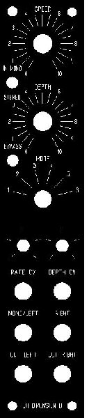
Here is my preliminary panel design for the DimD. I want it as compact as possible in a MOTM size panel. I've included all the bells and whistles that I could with the 2nd LFO with speed and depth pots as well as their associated CV inputs with attenuation pots just above the jacks.
I don't think I am missing anything or have added anything unnecessary, but if you see something out of place please let me know
Thanks,
Dave |
For Dim D emulation, you don't need the Rate and Depth stuff - that's handled in the Presets.
If you want to use the extra LFO (with Rate and Depth), I would add a switch to disable the Preset LFO. It's possible to use both LFOs, but I would at least want to have an option to turn th epreset LFO off.
You've probably noticed: The pins for many of the board-to-board connections on BBD Board and Main Board are located at the same position, so you might be able to stack the boards (with the right connectors) instead of using wires. (Not tested by me - I've only used wires because I have th eboards side by side in my prototype.)
JH.
_________________
"I tell you the truth, if anyone says to this mountain, 'Go, throw yourself into the sea,' and does not doubt in his heart but believes that what he says will happen, it will be done for him. Therefore I tell you, whatever you ask for in prayer, believe that you have received it, and it will be yours." (Mk 11,23f) |
|
|
Back to top
|
|
|
lexvortex
Joined: May 14, 2008
Posts: 155
Location: Toronto
|
|
|
Back to top
|
|
|
funkyfarm

Joined: Jan 21, 2007
Posts: 583
Location: France
Audio files: 3
|
| Posted: Wed Jan 28, 2009 5:56 pm Post subject:
|
|
|
Ahhh !
(your preview panel was a shame  ) ) |
|
|
Back to top
|
|
|
The Alison Project

Joined: Jul 21, 2006
Posts: 187
Location: Canada
Audio files: 2
|
| Posted: Sat Jan 31, 2009 5:32 pm Post subject:
|
|
|
Working on my DIM TD and beginning to think this is a build first, panel second project..
Couple questions thou, would it be worth it to put a DPDT toggle on the signal inversion points on the Tau Boards, I really like this on my Tau Phaser but not sure what it will be on the chorus..
Also I plan to add the second LFO from the BBD board and include a toggle to turn the preset LFO off, what exactly is the PHASE connections on the board.
Thanks
Chris
_________________
-
The Alison Project
www.thealisonproject.com
www.myspace.com/theyakuzacowboys |
|
|
Back to top
|
|
|
jhaible
Joined: May 25, 2007
Posts: 2014
Location: Germany
Audio files: 24
|
| Posted: Sun Feb 01, 2009 7:59 am Post subject:
|
|
|
| The Alison Project wrote: | Working on my DIM TD and beginning to think this is a build first, panel second project..
Couple questions thou, would it be worth it to put a DPDT toggle on the signal inversion points on the Tau Boards, I really like this on my Tau Phaser but not sure what it will be on the chorus.. |
Try it with jumpers, and see what you like best. If you like both settings, it makes sense to use that DPDT switch.
Unlike the "D" (where there's a vintage FX to emulate), the "T" isn't something that's really set. You see what you like best, and choose it. And then tell us!
| Quote: | what exactly is the PHASE connections on the board.
|
"Phase", when left open, means that BBD 1 and BBD 2 are modulated out of phase. (0deg and 180deg)
When closed (the two pins connected - attention: this is switching to -15V, not to GND! - see schematics), both BBDs are modulated in-phase.
That's important for emulating a Juno 6 chorus, where Mode 1 and Mode 2 means out-of-phase modulation (with different level and depth, of course), but pressing both buttons at once means in-phase modualtion 8with a 3rd rate and level).
JH.
_________________
"I tell you the truth, if anyone says to this mountain, 'Go, throw yourself into the sea,' and does not doubt in his heart but believes that what he says will happen, it will be done for him. Therefore I tell you, whatever you ask for in prayer, believe that you have received it, and it will be yours." (Mk 11,23f) |
|
|
Back to top
|
|
|
ach_gott
Joined: Sep 09, 2008
Posts: 79
Location: Chicago
|
| Posted: Mon Feb 09, 2009 4:20 pm Post subject:
|
|
|
| Now that I'm home from vacation, are there still boards available? If so, I'll place an order (I have the form). |
|
|
Back to top
|
|
|
jhaible
Joined: May 25, 2007
Posts: 2014
Location: Germany
Audio files: 24
|
| Posted: Tue Feb 10, 2009 1:44 am Post subject:
|
|
|
| ach_gott wrote: | | Now that I'm home from vacation, are there still boards available? If so, I'll place an order (I have the form). |
Yes, there are Subtle Chorus PCB sets left.
I guess the first boards I'm going to run out of, are the Tau PCBs, because a lot of people decided to go for the big "TD" option.
But at the moment, Tau's are still available, too.
JH.
_________________
"I tell you the truth, if anyone says to this mountain, 'Go, throw yourself into the sea,' and does not doubt in his heart but believes that what he says will happen, it will be done for him. Therefore I tell you, whatever you ask for in prayer, believe that you have received it, and it will be yours." (Mk 11,23f) |
|
|
Back to top
|
|
|
numbertalk
Joined: May 05, 2008
Posts: 992
Location: Austin, TX
Audio files: 5
|
| Posted: Sun Mar 01, 2009 4:17 am Post subject:
|
|
|
Hi JH,
Just looked at the documentation and had a couple questions.
1) For the remote bypass jack, is this for a NO momentary switch?
2) If I'm not planning on including XLR jacks, I'm assuming I'd go by the unbalanced 1/4" jack wiring diagram and that nothing is connected to the middle pin of the 2 input board connectors, right?
3) I'm not totally clear from the diagram (http://www.jhaible.heim.at/subtle_chorus/sc_audio_unbalanced.pdf) exactly how to wire up the 2 input jacks. These are mono switching jacks, right? For each of these jacks, the tip goes the right-most pin of its respective board connector, the sleeve goes to the left-most pin. But then it looks like for input 1 the sleeve lug is connected to the NC/switch lug, which is then chained to the switch lug of input 2 and finally this is further chained along to the right-most pin of the "Interf" board connect, is this right? Is that right most Interf pin a ground connection? I guess I'm thrown by the sleeve of input 1 being included here, since that seems to be grounded already via the input 1 board connector.
4) Finally, comparing the schematic (http://www.jhaible.heim.at/subtle_chorus/subtle_chorus_main_board_sch_dwg2.pdf) to the unbalanced outputs wiring diagram, in the wiring diagram, the pole of the mono/stereo switch is connected to the left most pin of Interf, but on the schematic, the left-most pin here is a ground connection - is this right? Does this server to grounding input 2 for the mono->stereo connection? If so, hopefully my 3rd question here will clear up the switched jack lugs and the grounded input 1 sleeve and how exactly these work with the 3rd pin of the Interf connector, if that is indeed *not* a ground connection.
Thanks for the help. |
|
|
Back to top
|
|
|
jhaible
Joined: May 25, 2007
Posts: 2014
Location: Germany
Audio files: 24
|
| Posted: Sun Mar 01, 2009 7:40 am Post subject:
|
|
|
| numbertalk wrote: |
1) For the remote bypass jack, is this for a NO momentary switch?
|
Right. No momentary switch.
| Quote: |
2) If I'm not planning on including XLR jacks, I'm assuming I'd go by the unbalanced 1/4" jack wiring diagram and that nothing is connected to the middle pin of the 2 input board connectors, right?
3) I'm not totally clear from the diagram (http://www.jhaible.heim.at/subtle_chorus/sc_audio_unbalanced.pdf) exactly how to wire up the 2 input jacks. These are mono switching jacks, right? For each of these jacks, the tip goes the right-most pin of its respective board connector, the sleeve goes to the left-most pin. But then it looks like for input 1 the sleeve lug is connected to the NC/switch lug, which is then chained to the switch lug of input 2 and finally this is further chained along to the right-most pin of the "Interf" board connect, is this right? Is that right most Interf pin a ground connection? I guess I'm thrown by the sleeve of input 1 being included here, since that seems to be grounded already via the input 1 board connector.
4) Finally, comparing the schematic (http://www.jhaible.heim.at/subtle_chorus/subtle_chorus_main_board_sch_dwg2.pdf) to the unbalanced outputs wiring diagram, in the wiring diagram, the pole of the mono/stereo switch is connected to the left most pin of Interf, but on the schematic, the left-most pin here is a ground connection - is this right? Does this server to grounding input 2 for the mono->stereo connection? If so, hopefully my 3rd question here will clear up the switched jack lugs and the grounded input 1 sleeve and how exactly these work with the 3rd pin of the Interf connector, if that is indeed *not* a ground connection.
Thanks for the help. |
My fault. I had the wrong pdf file up. The right one for unbalanced connection should be up by now:
http://www.jhaible.heim.at/subtle_chorus/sc_audio_unbalanced.pdf
Thanks for pointing this out!
JH.
_________________
"I tell you the truth, if anyone says to this mountain, 'Go, throw yourself into the sea,' and does not doubt in his heart but believes that what he says will happen, it will be done for him. Therefore I tell you, whatever you ask for in prayer, believe that you have received it, and it will be yours." (Mk 11,23f) |
|
|
Back to top
|
|
|
numbertalk
Joined: May 05, 2008
Posts: 992
Location: Austin, TX
Audio files: 5
|
| Posted: Sun Mar 01, 2009 1:27 pm Post subject:
|
|
|
Thank you!!!
| jhaible wrote: | | numbertalk wrote: |
1) For the remote bypass jack, is this for a NO momentary switch?
|
Right. No momentary switch.
| Quote: |
2) If I'm not planning on including XLR jacks, I'm assuming I'd go by the unbalanced 1/4" jack wiring diagram and that nothing is connected to the middle pin of the 2 input board connectors, right?
3) I'm not totally clear from the diagram (http://www.jhaible.heim.at/subtle_chorus/sc_audio_unbalanced.pdf) exactly how to wire up the 2 input jacks. These are mono switching jacks, right? For each of these jacks, the tip goes the right-most pin of its respective board connector, the sleeve goes to the left-most pin. But then it looks like for input 1 the sleeve lug is connected to the NC/switch lug, which is then chained to the switch lug of input 2 and finally this is further chained along to the right-most pin of the "Interf" board connect, is this right? Is that right most Interf pin a ground connection? I guess I'm thrown by the sleeve of input 1 being included here, since that seems to be grounded already via the input 1 board connector.
4) Finally, comparing the schematic (http://www.jhaible.heim.at/subtle_chorus/subtle_chorus_main_board_sch_dwg2.pdf) to the unbalanced outputs wiring diagram, in the wiring diagram, the pole of the mono/stereo switch is connected to the left most pin of Interf, but on the schematic, the left-most pin here is a ground connection - is this right? Does this server to grounding input 2 for the mono->stereo connection? If so, hopefully my 3rd question here will clear up the switched jack lugs and the grounded input 1 sleeve and how exactly these work with the 3rd pin of the Interf connector, if that is indeed *not* a ground connection.
Thanks for the help. |
My fault. I had the wrong pdf file up. The right one for unbalanced connection should be up by now:
http://www.jhaible.heim.at/subtle_chorus/sc_audio_unbalanced.pdf
Thanks for pointing this out!
JH. |
|
|
|
Back to top
|
|
|
lexvortex
Joined: May 14, 2008
Posts: 155
Location: Toronto
|
|
|
Back to top
|
|
|
jhaible
Joined: May 25, 2007
Posts: 2014
Location: Germany
Audio files: 24
|
Posted: Thu Mar 19, 2009 10:19 am Post subject:
Subject description: Building DimD |
|
|
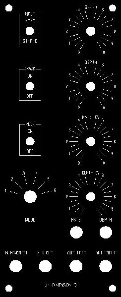
| lexvortex wrote: | Hi JH,
I am starting in on the build of the DimD and have a few questions regarding potentiometer values. I will be using the panel shown below but don't know what value pots to use. Should 100k lin be fine for all? I am using the original DimD circuit as well as the extra LFO on the BBD board.
Thanks,
Dave |
For Depth CV, a smaller value will be better. Like 10k, 22k or 47k.
JH.
_________________
"I tell you the truth, if anyone says to this mountain, 'Go, throw yourself into the sea,' and does not doubt in his heart but believes that what he says will happen, it will be done for him. Therefore I tell you, whatever you ask for in prayer, believe that you have received it, and it will be yours." (Mk 11,23f) |
|
|
Back to top
|
|
|
lexvortex
Joined: May 14, 2008
Posts: 155
Location: Toronto
|
| Posted: Thu Mar 19, 2009 1:52 pm Post subject:
|
|
|
Great!! Thanks 
Dave |
|
|
Back to top
|
|
|
|

 Forum index » DIY Hardware and Software » Jürgen Haible designs