| Author |
Message |
slacker
Joined: Nov 18, 2007
Posts: 301
Location: England
Audio files: 11
G2 patch files: 1
|
 Posted: Tue Apr 07, 2009 2:37 pm Post subject: Posted: Tue Apr 07, 2009 2:37 pm Post subject:
|
  |
|
It uses a high frequency clock which is around 30Khz. This then gets mixed with what ever CV you feed it and that creates a pulse width modulated signal that drives the 4066s. Basically the CV sets the width of the pulse and that sets the resistance of the 4066.
I haven't heard any bleedthrough yet, there is a bit of noise if you sweep the filter really high, but that might not be from the clock.
The original schematic is here http://www.generalguitargadgets.com/pdf/ggg_mxr_envelope_filter_mods.pdf. I've just removed the envelope follower, that's everything from R8 to R23. The CV in goes through a resistor to pin 9 of A1d. The CV response is reversed like this though so I just added a second invertor like the "reverse sweep" mod. Apart from that I just tweaked a few things to improve the frequency range.
The clock is made up of A1a, A1b and A1c. |
|
|
Back to top
|
|
 |
synthmonger
Joined: Nov 16, 2006
Posts: 578
Location: flada
Audio files: 3
|
| Posted: Tue Apr 07, 2009 2:56 pm Post subject:
|
|
|
| Well I'll be! I didn't think of using a 4069 as the clocking vco. You should try and work out a sync function. Osamu has a vco that has a faux sync with a 4069 as a vco. I tried it and it works great. |
|
|
Back to top
|
|
|
synthmonger
Joined: Nov 16, 2006
Posts: 578
Location: flada
Audio files: 3
|
| Posted: Tue Apr 07, 2009 3:07 pm Post subject:
|
|
|
Here's a sync demo of my vco clocking 4066 switches in my wasp like vcf. The filters are almost identical, just different caps but both state variable. Mine will self-oscillate though.
http://www.youtube.com/watch?v=RFMUEMy4KI8 |
|
|
Back to top
|
|
|
synthmonger
Joined: Nov 16, 2006
Posts: 578
Location: flada
Audio files: 3
|
| Posted: Tue Apr 07, 2009 3:50 pm Post subject:
|
|
|
| I think I Just figured out how to add a pseudo-sync function to the resonate filter. Gotta love it when things work in threes.... |
|
|
Back to top
|
|
|
loss1234

Joined: Jul 24, 2007
Posts: 1536
Location: nyc
Audio files: 41
|
|
|
Back to top
|
|
|
synthmonger
Joined: Nov 16, 2006
Posts: 578
Location: flada
Audio files: 3
|
| Posted: Wed Apr 08, 2009 8:33 am Post subject:
|
|
|
| loss1234 wrote: | what is this pseudo sync mod?
sounds cool
also..you mentioned you left out a chip on the schematic...where does that go? at the very end
i really want to build this but i am a bit scared of your schematic 
seriously though this is a super project
thanks |
Using yet another 4007 as a switch to swap out the 1nF caps. The left out chip is just one of the 3 that replace the vactrols. |
|
|
Back to top
|
|
|
slacker
Joined: Nov 18, 2007
Posts: 301
Location: England
Audio files: 11
G2 patch files: 1
|
| Posted: Wed Apr 08, 2009 1:11 pm Post subject:
|
|
|
| synthmonger wrote: | | Well I'll be! I didn't think of using a 4069 as the clocking vco. You should try and work out a sync function. Osamu has a vco that has a faux sync with a 4069 as a vco. I tried it and it works great. |
Cool, I'll give that a try, I know the VCO you mean.
I don't suppose you've done a VCA have you? I'm looking for something for my CMOS synth idea. |
|
|
Back to top
|
|
|
synthmonger
Joined: Nov 16, 2006
Posts: 578
Location: flada
Audio files: 3
|
| Posted: Wed Apr 08, 2009 1:44 pm Post subject:
|
|
|
I'm working on a single chip VCA using the 4007 and a tripple using a 4007 and 4069. It's 4th on my list right now though.
Of the 4007 VCA's I found on the net; I tried Osamu's, Rene's and one I found in an ETI article. The eti one worked the best but not as good as I'd hope. |
|
|
Back to top
|
|
|
v-un-v
Janitor


Joined: May 16, 2005
Posts: 8933
Location: Birmingham, England, UK
Audio files: 11
G2 patch files: 1
|
| Posted: Wed Apr 08, 2009 3:42 pm Post subject:
|
|
|
Other thread alert (re CMOS vocoder)!!!;
http://www.electro-music.com/forum/topic-27272.html
Introducing Mr Stephen Giles! 
_________________
ACHTUNG!
ALLES TURISTEN UND NONTEKNISCHEN LOOKENPEEPERS!
DAS KOMPUTERMASCHINE IST NICHT FÜR DER GEFINGERPOKEN UND MITTENGRABEN! ODERWISE IST EASY TO SCHNAPPEN DER SPRINGENWERK, BLOWENFUSEN UND POPPENCORKEN MIT SPITZENSPARKSEN.
IST NICHT FÜR GEWERKEN BEI DUMMKOPFEN. DER RUBBERNECKEN SIGHTSEEREN KEEPEN DAS COTTONPICKEN HÄNDER IN DAS POCKETS MUSS.
ZO RELAXEN UND WATSCHEN DER BLINKENLICHTEN. |
|
|
Back to top
|
|
|
synthmonger
Joined: Nov 16, 2006
Posts: 578
Location: flada
Audio files: 3
|
|
|
Back to top
|
|
|
richardc64

Joined: Jun 01, 2006
Posts: 679
Location: NYC
Audio files: 26
|
|
|
Back to top
|
|
|
loss1234
Joined: Jul 24, 2007
Posts: 1536
Location: nyc
Audio files: 41
|
|
|
Back to top
|
|
|
synthmonger
Joined: Nov 16, 2006
Posts: 578
Location: flada
Audio files: 3
|
| Posted: Thu Apr 09, 2009 8:28 am Post subject:
|
|
|
| True these aren't as simple as one would expect in a Lunetta design. Though it is possible to remove a lot of the components to make them Lunetta. I'll post a more Lunetta version when it's finished. |
|
|
Back to top
|
|
|
synthmonger
Joined: Nov 16, 2006
Posts: 578
Location: flada
Audio files: 3
|
| Posted: Thu Apr 09, 2009 8:33 am Post subject:
|
|
|
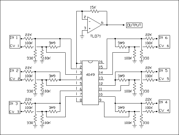
| How does that Hex VCA even work? Seems like it wouldn't due to the pins. |
|
|
Back to top
|
|
|
Rykhaard
Joined: Sep 02, 2007
Posts: 1290
Location: Canada
|
| Posted: Thu Apr 09, 2009 8:50 am Post subject:
|
|
|
| synthmonger wrote: | | How does that Hex VCA even work? Seems like it wouldn't due to the pins. |
Aye. The Vdd and Vss are connected together to the input of the output opamp??
I don't see where each of the 6 'outputs' are summed to the input of the opamp either ......  |
|
|
Back to top
|
|
|
slacker
Joined: Nov 18, 2007
Posts: 301
Location: England
Audio files: 11
G2 patch files: 1
|
| Posted: Thu Apr 09, 2009 8:57 am Post subject:
|
|
|
| I think that VCA is using the gates as voltage controlled resistors, similar to what you're doing with 4007s. If you look at a data sheet that has a schematic of the individual inverters it sort of makes sense. |
|
|
Back to top
|
|
|
Rykhaard
Joined: Sep 02, 2007
Posts: 1290
Location: Canada
|
| Posted: Thu Apr 09, 2009 9:09 am Post subject:
|
|
|
| slacker wrote: | | I think that VCA is using the gates as voltage controlled resistors, similar to what you're doing with 4007s. If you look at a data sheet that has a schematic of the individual inverters it sort of makes sense. |
On that posted schematic though, the VCA's outputs aren't going anywhere ...... ? I could bread board one of them of course and see what happens.  |
|
|
Back to top
|
|
|
slacker
Joined: Nov 18, 2007
Posts: 301
Location: England
Audio files: 11
G2 patch files: 1
|
| Posted: Thu Apr 09, 2009 9:23 am Post subject:
|
|
|
| Rykhaard wrote: |
On that posted schematic though, the VCA's outputs aren't going anywhere ...... ? |
I think it makes sense if you look at it as being made up of individual PMOS and NMOS transistors rather than, them being inverter gates.
I think it's basically similar to the VCA from this http://www.uni-bonn.de/~uzs159/vcf4007_s.gif. Pins 1 and 8 on the Hex VCA are the same as pin 7 on Rene's. The outputs are pin 8 and the inputs are pin 6.
Last edited by slacker on Thu Apr 09, 2009 9:38 am; edited 2 times in total |
|
|
Back to top
|
|
|
synthmonger
Joined: Nov 16, 2006
Posts: 578
Location: flada
Audio files: 3
|
| Posted: Thu Apr 09, 2009 9:27 am Post subject:
|
|
|
| Ahh that makes sense now. Pretty clever. |
|
|
Back to top
|
|
|
slacker
Joined: Nov 18, 2007
Posts: 301
Location: England
Audio files: 11
G2 patch files: 1
|
| Posted: Thu Apr 09, 2009 9:43 am Post subject:
|
|
|
Yeah I think you're right, this stuff is definitely stretching the definition of a Lunetta. Nothing wrong with a bit of crossover though in my opinion, after all some people have integrated bits of Lunetta stuff into their modulars.
If I post my filter ideas I'll do it in the general DIY section, hopefully they'll be gentle with me 
Thanks for posting that VCA though, I'll try it out. |
|
|
Back to top
|
|
|
synthmonger
Joined: Nov 16, 2006
Posts: 578
Location: flada
Audio files: 3
|
| Posted: Thu Apr 09, 2009 10:16 am Post subject:
|
|
|
| I should follow your route slacker and if I can post a Lunetta version here. |
|
|
Back to top
|
|
|
loss1234
Joined: Jul 24, 2007
Posts: 1536
Location: nyc
Audio files: 41
|
| Posted: Thu Apr 09, 2009 10:27 am Post subject:
|
|
|
synthmonger....the more i look at the schematic..the more i get a bit confused...
i feel like an idiot so sorry if i keep bothering you about this
Ok for the Stage that gets repeated three times....each stage has A and B to control its resistance right? SO my question is...DO i need to make a completely NEW A and B fake vactrol for each stage? (which would mean stage 2 would have C and D, stage three E and F,etc)so a total of 6 4007 based vactrols? Or can i just stick the same out point from A and B to the new stage?
what i am trying to do is redraw it out so i can follow it.
also...in between each stage..do i put a 100k resistor or a cap?
thanks
_________________
-------------------------------------------- check out various dan music at: http://www.myspace.com/lossnyc
http://www.myspace.com/snazelle
http://www.soundclick.com/lossnyc.htm http://www.indie911.com/dan-snazelle |
|
|
Back to top
|
|
|
synthmonger
Joined: Nov 16, 2006
Posts: 578
Location: flada
Audio files: 3
|
| Posted: Thu Apr 09, 2009 10:38 am Post subject:
|
|
|
| loss1234 wrote: | synthmonger....the more i look at the schematic..the more i get a bit confused...
i feel like an idiot so sorry if i keep bothering you about this
Ok for the Stage that gets repeated three times....each stage has A and B to control its resistance right? SO my question is...DO i need to make a completely NEW A and B fake vactrol for each stage? (which would mean stage 2 would have C and D, stage three E and F,etc)so a total of 6 4007 based vactrols? Or can i just stick the same out point from A and B to the new stage?
what i am trying to do is redraw it out so i can follow it.
also...in between each stage..do i put a 100k resistor or a cap?
thanks |
My schematic is a big bag off mess, I can totally understand your confusion.
Yeah you need to replace each vactrol with a new 4007. You only one 4007 per stage and only one master resonance CV (this doesn't get repeated). So you have three 4007s for cut off control and only one 4007 for Master Resonance CV.
Just a cap between each stage. They sum together at the input and their outputs go to seperate stages.
Check Fonik's resonators for help. I based mine off that, which is identical to the Korgs but much easier to read. |
|
|
Back to top
|
|
|
v-un-v
Janitor
Joined: May 16, 2005
Posts: 8933
Location: Birmingham, England, UK
Audio files: 11
G2 patch files: 1
|
| Posted: Thu Apr 09, 2009 5:08 pm Post subject:
|
|
|
Who thinks this thread should be moved? Is it getting a bit big for its Lunetta boots? I rather like that this thread is within this section, as it is CMOS based, therefore it's pretty nuts, but then again, were getting a bit too confused between something simple and something complex- especially with all these vactrols now being mentioned.
Votes please (although Mosc really should have the last word )
_________________
ACHTUNG!
ALLES TURISTEN UND NONTEKNISCHEN LOOKENPEEPERS!
DAS KOMPUTERMASCHINE IST NICHT FÜR DER GEFINGERPOKEN UND MITTENGRABEN! ODERWISE IST EASY TO SCHNAPPEN DER SPRINGENWERK, BLOWENFUSEN UND POPPENCORKEN MIT SPITZENSPARKSEN.
IST NICHT FÜR GEWERKEN BEI DUMMKOPFEN. DER RUBBERNECKEN SIGHTSEEREN KEEPEN DAS COTTONPICKEN HÄNDER IN DAS POCKETS MUSS.
ZO RELAXEN UND WATSCHEN DER BLINKENLICHTEN. |
|
|
Back to top
|
|
|
synthmonger
Joined: Nov 16, 2006
Posts: 578
Location: flada
Audio files: 3
|
| Posted: Thu Apr 09, 2009 5:41 pm Post subject:
|
|
|
| The Vactrols are apart of the Korg Resonator schematic -not mine. I simply replaced them with PMOS transistors from a 4007. |
|
|
Back to top
|
|
|
|

 Forum index » DIY Hardware and Software » Lunettas - circuits inspired by Stanley Lunetta