| Author |
Message |
skrasms
Joined: Feb 21, 2008
Posts: 121
Location: Portland, OR
|
 Posted: Sun Nov 08, 2009 5:20 pm Post subject:
Verilog Sigma Delta D/A Converter Posted: Sun Nov 08, 2009 5:20 pm Post subject:
Verilog Sigma Delta D/A Converter |
  |
|
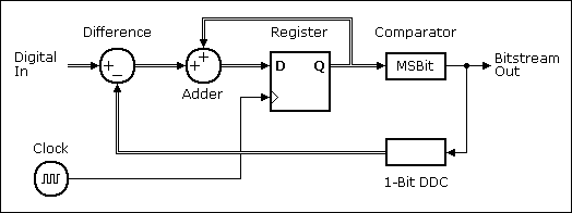
It might not be possible to do decent quality A/D using only an FPGA, but a decent quality sigma delta D/A seems reasonable. I'm trying to work my way up to a second order sigma delta D/A from scratch. I started with this diagram of a digital first order converter that I found online:

I attempted a quick literal translation into Verilog like this:
| Code: |
module test(
input unsigned [3:0] INVAL, //input value, 0 to 15
output BITSTREAM, //output bit stream
input CLK, //input clock
output wire signed [9:0] delta, //Difference signal
output wire signed [9:0] sigma, //Sum signal
output wire signed [6:0] feedback, //Feedback from comparator
output reg signed [9:0] d_out //Flip flop output
);
assign delta = (d_out>256) ? INVAL - 15 : INVAL + 15;
assign sigma = delta + d_out;
assign feedback = (d_out>256) ? 15 : -15;
assign BITSTREAM = (d_out>256);
always @(posedge CLK)
d_out <= sigma;
endmodule
|
The lowercase names are "internal" signals that I made into outputs for quicker simulation troubleshooting in Quartus.
Unfortunately, the average output range appears to be 0.5 to 1.0 instead of 0.0 to 1.0. I'm pretty sure there is something wrong about the way I'm handling the feedback. What size should it be? How many bits larger should the accumulator be than the input signal? There is a lot I still need to sit down and figure out, but someone who's done this before could probably point me in the right direction must faster.
Has anyone messed around with this stuff? I found a paper on 3rd and 5th order converters, but their implementations use more gates than my Cyclone I has.
_________________
Software and Hardware Design |
|
|
Back to top
|
|
 |
skrasms
Joined: Feb 21, 2008
Posts: 121
Location: Portland, OR
|
 Posted: Sun Nov 08, 2009 7:14 pm Post subject: Posted: Sun Nov 08, 2009 7:14 pm Post subject:
|
  |
|
I found a Xilinx app note about a first order implementation. It only uses 12 logic units on a Cyclone I. I edited their code to make it more readable (to me):
| Code: |
module test(
output reg DACout, //Average Output feeding analog lowpass
input [MSBI:0] DACin, //DAC input (excess 2**MSBI)
input CLK,
input RESET
);
parameter MSBI = 7;
reg [MSBI+2:0] DeltaAdder; //Output of Delta Adder
reg [MSBI+2:0] SigmaAdder; //Output of Sigma Adder
reg [MSBI+2:0] SigmaLatch; //Latches output of Sigma Adder
reg [MSBI+2:0] DeltaB; //B input of Delta Adder
always @ (*)
DeltaB = {SigmaLatch[MSBI+2], SigmaLatch[MSBI+2]} << (MSBI+1);
always @(*)
DeltaAdder = DACin + DeltaB;
always @(*)
SigmaAdder = DeltaAdder + SigmaLatch;
always @(posedge CLK or posedge RESET)
if(RESET) begin
SigmaLatch <= 1'b1 << (MSBI+1);
DACout <= 1'b0;
end else begin
SigmaLatch <= SigmaAdder;
DACout <= SigmaLatch[MSBI+2];
end
endmodule
|
That simulates perfectly, and is pretty fun to watch. It's still only first order, though. There is a lot to be gained just by getting it up to second order.
_________________
Software and Hardware Design |
|
|
Back to top
|
|
 |
skrasms
Joined: Feb 21, 2008
Posts: 121
Location: Portland, OR
|
 Posted: Sun Nov 08, 2009 9:39 pm Post subject: Posted: Sun Nov 08, 2009 9:39 pm Post subject:
|
  |
|
I tried the most obvious way of changing the code to second order just by adding another delta-sigma-latch block into the series. Both blocks get the same feedback, which is how I understand second order works.
Sadly that does not work. It just couldn't be *that* easy.
_________________
Software and Hardware Design
Last edited by skrasms on Fri Nov 20, 2009 11:40 pm; edited 1 time in total |
|
|
Back to top
|
|
 |
skrasms
Joined: Feb 21, 2008
Posts: 121
Location: Portland, OR
|
 Posted: Mon Nov 09, 2009 12:24 am Post subject: Posted: Mon Nov 09, 2009 12:24 am Post subject:
|
  |
|
Ken Pohlman's book "Principles of Digital Audio" has a block diagram of a second order delta sigma modulator, and it uses different feedback gain values between the two sections: -1 and 2. I wrote an Octave script to test it, and it seems to work well. It needs twos complement math, but it looks like the multiplications can be done using shifts and simple logic.
_________________
Software and Hardware Design |
|
|
Back to top
|
|
 |
JovianPyx

Joined: Nov 20, 2007
Posts: 1988
Location: West Red Spot, Jupiter
Audio files: 224
|
 Posted: Mon Nov 09, 2009 2:17 pm Post subject: Posted: Mon Nov 09, 2009 2:17 pm Post subject:
|
  |
|
As a fellow FPGA user, I am interested in what you are doing. Thanks for posting your findings. My own Verilog code work has gone toward the development of the guts of several synthesizers (see sig link). Three of those synths use 24 bit stereo delta-sigma hardware DACs and they work very well. I have 4 synth (FPGA dev) boards that have a 12 bit resistor ladder DAC and they actually sound pretty good, but your project would allow me to try a delta-sigma DAC - hopefully at 24 bits.
Good luck with this and please keep us informed.
_________________
FPGA, dsPIC and Fatman Synth Stuff
Time flies like a banana.
Fruit flies when you're having fun.
BTW, Do these genes make my ass look fat?
corruptio optimi pessima
|
|
|
Back to top
|
|
 |
jksuperstar

Joined: Aug 20, 2004
Posts: 2503
Location: Denver
Audio files: 1
G2 patch files: 18
|
 Posted: Mon Nov 09, 2009 5:13 pm Post subject: Posted: Mon Nov 09, 2009 5:13 pm Post subject:
|
  |
|
Great little project.
As to your original design, be careful mixing signed and unsigned values with various bit widths. These types of designs don't typically depend on the verilog compiler to figure out all the bits for you like a high level programming language would; instead they are generally forced to a fixed point integer system, and scaling is done very carefully.
For example, you have INVAL as an unsigned input, but then in the delta calculation, you add/subtract 15 (which is also the limit of INVAL's value). That's an assumption that the compiler automatically converts the unsigned number into a signed number first, then adds/subtracts 15, then extends the bit width to match the 'delta' size of 10 bits.
I'd recommend first converting the unsigned 4 bit value to a signed 10 bit one, then use that value for calculations. |
|
|
Back to top
|
|
 |
skrasms
Joined: Feb 21, 2008
Posts: 121
Location: Portland, OR
|
 Posted: Tue Nov 10, 2009 12:13 am Post subject: Posted: Tue Nov 10, 2009 12:13 am Post subject:
|
  |
|
| ScottG wrote: | As a fellow FPGA user, I am interested in what you are doing. Thanks for posting your findings. My own Verilog code work has gone toward the development of the guts of several synthesizers (see sig link). Three of those synths use 24 bit stereo delta-sigma hardware DACs and they work very well. I have 4 synth (FPGA dev) boards that have a 12 bit resistor ladder DAC and they actually sound pretty good, but your project would allow me to try a delta-sigma DAC - hopefully at 24 bits.
Good luck with this and please keep us informed. |
Thanks for the encouragement 
Even a nice "24-bit" audio D/A like the Cirrus Logic CS4398 is only about 18 usable bits (-107dB THD+N). I think the laws of physics put a hard stop slightly after 20 bits, but I don't have any proof handy. By that point it's a fight against the resistance of the bond wires that go from the die to the outside world.
In terms of the math, the 24 bits available from a second order system won't really be better than the 24 bits available with a first order system... they'll just be easier to get (less clock speed required). If you change the MSBI parameter in that edited Xilinx code, it'll do 24 bits as-is. For 24-bit quality at 20 kHz it'll need the clock running at least 107 MHz. That is completely reasonable given how little hardware it actually needs. Quartus says I'm safe to run it well past 200 MHz on a Cyclone I.
Using simple PWM (no noise shaping or anything fancy) it would take a clock running somewhere around 703687441800 MHz. I'm not making that up 
Going the other direction, a second order delta sigma system would only need about 20 MHz to get 24-bit quality at 20 kHz.
I think the limiting factor of the actual audio output from a delta sigma in an FPGA will be the internal clock Jitter. At these speeds and bit depths it only takes picoseconds of error to make audible artifacts. I'm really interested in getting some measurements.
_________________
Software and Hardware Design
Last edited by skrasms on Tue Nov 10, 2009 12:24 am; edited 1 time in total |
|
|
Back to top
|
|
 |
skrasms
Joined: Feb 21, 2008
Posts: 121
Location: Portland, OR
|
 Posted: Tue Nov 10, 2009 12:19 am Post subject: Posted: Tue Nov 10, 2009 12:19 am Post subject:
|
  |
|
| jksuperstar wrote: | Great little project.
As to your original design, be careful mixing signed and unsigned values with various bit widths. These types of designs don't typically depend on the verilog compiler to figure out all the bits for you like a high level programming language would; instead they are generally forced to a fixed point integer system, and scaling is done very carefully.
For example, you have INVAL as an unsigned input, but then in the delta calculation, you add/subtract 15 (which is also the limit of INVAL's value). That's an assumption that the compiler automatically converts the unsigned number into a signed number first, then adds/subtracts 15, then extends the bit width to match the 'delta' size of 10 bits.
I'd recommend first converting the unsigned 4 bit value to a signed 10 bit one, then use that value for calculations. |
You pointed this out just as I was getting more in depth with my testing, and it cleared up a lot of my confusion. I thought Verilog handled more than it does.
I spent a good chunk of time tonight learning how to properly add two's complement numbers without overflowing.
_________________
Software and Hardware Design |
|
|
Back to top
|
|
 |
jksuperstar

Joined: Aug 20, 2004
Posts: 2503
Location: Denver
Audio files: 1
G2 patch files: 18
|
 Posted: Tue Nov 10, 2009 7:04 am Post subject: Posted: Tue Nov 10, 2009 7:04 am Post subject:
|
  |
|
Software programming languages can make these assumptions, since the definitions of bytes, words, longwords is somewhat arbitrary, while the hardware it is compiling to is fixed..not changeable. So, the target is a known thing, and therefore much easier to make assumptions for.
With Verilog and VHDL, your hardware can be anything, and many strange forms of math exist and are exploited to deal with the idea of binary numbers (Galois Fields for example). So, it's almost impossible for the compiler to figure out what is "right", since if it did that, the designer would no longer have complete control, which is paramount for hardware design! (insert Muahahaha laughter here for full effect).
Of course, on the flip side, complete control is an illusion, and the compiler does lots of things like boiling down your logic to the fastest or smallest design it can think of that's equivalent, but most compilers have some switches and variables you can set to override it's default mode of thinking. In your case, however, I'd steer towards working out all the bus widths by hand. If you need to, or can, make the widths much larger than they need to be, then you can see in simulation what bits are really being used, and how they are used. |
|
|
Back to top
|
|
 |
jksuperstar

Joined: Aug 20, 2004
Posts: 2503
Location: Denver
Audio files: 1
G2 patch files: 18
|
 Posted: Tue Nov 10, 2009 4:01 pm Post subject: Posted: Tue Nov 10, 2009 4:01 pm Post subject:
|
  |
|
Oh, one other very important thing to keep a watchful eye on: the fixed point! What parts of the number are defined to be "magnitude" and what is "fractional" makes for most of the fun and nearly all of the pain in DSP  |
|
|
Back to top
|
|
 |
JovianPyx

Joined: Nov 20, 2007
Posts: 1988
Location: West Red Spot, Jupiter
Audio files: 224
|
 Posted: Tue Nov 10, 2009 7:07 pm Post subject: Posted: Tue Nov 10, 2009 7:07 pm Post subject:
|
  |
|
Yeah, that's where all the fun is...  All good points. All good points.
I use similar methods to determine the best widths for different pieces of data.
_________________
FPGA, dsPIC and Fatman Synth Stuff
Time flies like a banana.
Fruit flies when you're having fun.
BTW, Do these genes make my ass look fat?
corruptio optimi pessima
|
|
|
Back to top
|
|
 |
skrasms
Joined: Feb 21, 2008
Posts: 121
Location: Portland, OR
|
 Posted: Wed Nov 11, 2009 9:35 pm Post subject: Posted: Wed Nov 11, 2009 9:35 pm Post subject:
|
  |
|
I've done lots of fixed point math, but never signed. I'd always convert to unsigned first and then process so that I wouldn't have to think about it.
I finally put all the code in place for a 16-bit 2nd order signed version. The first thing it does is sign-extend the input to 25 bits.
It doesn't work yet, of course, but here's the current code:
| Code: |
module siggit(
input signed [15:0] INVAL, //16-bit signed number, -1 to 1
input CLK,
input RESET,
output reg BITSTREAM
);
reg [24:0] inval_x; //25-bit signed number, S8.16
reg [24:0] DeltaAdder1;
reg [25:0] DeltaAdder1_x; //anything ending in _x
reg [24:0] DeltaAdder2; //is the result of a signed sum
reg [25:0] DeltaAdder2_x;
reg [24:0] SigmaAdder1;
reg [25:0] SigmaAdder1_x;
reg [24:0] SigmaAdder2;
reg [25:0] SigmaAdder2_x;
reg [24:0] SigmaLatch1;
reg [24:0] SigmaLatch2;
reg [24:0] Limit_FB; //Feedback signal with protection
reg [24:0] Limit_FB_neg; //Negative protected feedback
reg [24:0] Limit_FB_2x; //Negative protected feedback x2
reg [25:0] FB; //Feedback, SigmaLatch2 - Quant
reg [24:0] Quant; //Quantizer Output: -1 or +1
reg [24:0] Quant_neg;
always @(*) Quant_neg <= (~Quant) + 1;
//Quantizer output * -1
always @(*) Quant <= SigmaLatch2[24] ? {{10{1'b1}}, 15'b0} : {1'b1, 15'b0};
//The Quantizer outputs either +1 or -1
always @(*) FB <= {Quant_neg[24], Quant_neg} + {SigmaLatch2[24], SigmaLatch2};
//Feedback is second sigma latch minus Quantizer output
always @(*) Limit_FB <= {FB[25]&FB[24], FB[23:0]};
//No actual limiting at the moment, just reducing the bit width by one
always @(*) Limit_FB_2x <= {Limit_FB[24], Limit_FB[22:0], 1'b0};
//Signed multiply by 2
always @(*) inval_x <= {{9{INVAL[15]}}, INVAL};
//Sign extend input value 9 bits to go from 16 to 25
always @(*) Limit_FB_neg <= (~Limit_FB) + 1;
//Limited feedback value * -1
always @(*) SigmaAdder1_x <= {SigmaLatch1[24], SigmaLatch1} + {DeltaAdder1[24], DeltaAdder1};
//Signed addition
always @(*) SigmaAdder1 <= {SigmaAdder1_x[25]&SigmaAdder1_x[24], SigmaAdder1_x[23:0]};
//Shrink result one bit
always @(*) SigmaAdder2_x <= {SigmaLatch2[24], SigmaLatch2} + {DeltaAdder2[24], DeltaAdder2};
//Signed addition
always @(*) SigmaAdder2 <= {SigmaAdder2_x[25]&SigmaAdder2_x[24], SigmaAdder2_x[23:0]};
//Shrink result one bit
always @(*) DeltaAdder1_x <= {inval_x[24], inval_x} + {Limit_FB_neg[24], Limit_FB_neg};
//Signed addition
always @(*) DeltaAdder1 <= {DeltaAdder1_x[25]&DeltaAdder1_x[24], DeltaAdder1_x[23:0]};
//Shrink
always @(*) DeltaAdder2_x <= {SigmaLatch1[24], SigmaLatch1} + {Limit_FB_2x[24], Limit_FB_2x};
//Signed add
always @(*) DeltaAdder2 <= {DeltaAdder2_x[25]&DeltaAdder2_x[24], DeltaAdder2_x[23:0]};
//Shrink
always @(posedge CLK or posedge RESET)
if(RESET) begin
SigmaLatch1 <= 1'b0; //Initial values... anything special?
SigmaLatch2 <= 1'b0; //Testing...
BITSTREAM <= 1'b0;
end else begin
//Each sigma sum is cut back to 24-bit when latched
SigmaLatch1 <= {SigmaAdder1_x[25]&SigmaAdder1_x[24], SigmaAdder1_x[23:0]};
SigmaLatch2 <= {SigmaAdder2_x[25]&SigmaAdder2_x[24], SigmaAdder2_x[23:0]};
BITSTREAM <= Quant[24];
end
endmodule
|
Right now the system keeps converging to a point where everything balances and all movement stops. I'm adding functions to my test bench to handle the conversions from signed fixed point into decimal. Looking at giant signed integers isn't so helpful.
Go math!
_________________
Software and Hardware Design |
|
|
Back to top
|
|
 |
skrasms
Joined: Feb 21, 2008
Posts: 121
Location: Portland, OR
|
 Posted: Wed Nov 11, 2009 11:31 pm Post subject: Posted: Wed Nov 11, 2009 11:31 pm Post subject:
|
  |
|
Oh whoops, that isn't structured correctly at all. It's doing what it should do given that code, but the code doesn't match the block diagram. At least the signed fixed point math is working in simulation.
_________________
Software and Hardware Design |
|
|
Back to top
|
|
 |
skrasms
Joined: Feb 21, 2008
Posts: 121
Location: Portland, OR
|
 Posted: Wed Nov 11, 2009 11:44 pm Post subject: Posted: Wed Nov 11, 2009 11:44 pm Post subject:
|
  |
|
Oh hey, I made the code match the block diagram, and it looks like it's actually working!
| Code: |
module siggit(
input signed [15:0] INVAL, //16-bit signed number, -1 to 1
input CLK,
input RESET,
output reg BITSTREAM
);
reg [24:0] inval_x; //25-bit signed number, S8.16
reg [24:0] SigmaAdder1;
reg [25:0] SigmaAdder1_x;
reg [24:0] SigmaAdder2;
reg [25:0] SigmaAdder2_x;
reg [24:0] SigmaLatch1;
reg [24:0] SigmaLatch2;
reg [24:0] Limit_FB; //Feedback signal with protection
reg [24:0] Limit_FB_neg; //Negative protected feedback
reg [24:0] Limit_FB_2x; //Negative protected feedback x2
reg [25:0] FB; //Feedback, SigmaLatch2 - Quant
reg [24:0] Quant; //Quantizer Output: -1 or +1
reg [24:0] Quant_neg;
always @(*) Quant_neg <= (~Quant) + 1;
//Quantizer output * -1
always @(*) Quant <= SigmaLatch2[24] ? {{10{1'b1}}, 15'b0} : {1'b1, 15'b0};
//The Quantizer outputs either +1 or -1
always @(*) FB <= {Quant_neg[24], Quant_neg} + {SigmaLatch2[24], SigmaLatch2};
//Feedback is second sigma latch minus Quantizer output
always @(*) Limit_FB <= {FB[25]&FB[24], FB[23:0]};
//No actual limiting at the moment, just reducing the bit width by one
always @(*) Limit_FB_2x <= {Limit_FB[24], Limit_FB[22:0], 1'b0};
//Signed multiply by 2
always @(*) inval_x <= {{9{INVAL[15]}}, INVAL};
//Sign extend input value 9 bits to go from 16 to 25
always @(*) Limit_FB_neg <= (~Limit_FB) + 1;
//Limited feedback value * -1
always @(*) SigmaAdder1_x <= {inval_x[24], inval_x} + {Limit_FB_neg[24], Limit_FB_neg};
//Signed addition
always @(*) SigmaAdder1 <= {SigmaAdder1_x[25]&SigmaAdder1_x[24], SigmaAdder1_x[23:0]};
//Shrink result one bit
always @(*) SigmaAdder2_x <= {SigmaLatch1[24], SigmaLatch1} + {Limit_FB_2x[24], Limit_FB_2x};
//Signed addition
always @(*) SigmaAdder2 <= {SigmaAdder2_x[25]&SigmaAdder2_x[24], SigmaAdder2_x[23:0]};
//Shrink result one bit
always @(posedge CLK or posedge RESET)
if(RESET) begin
SigmaLatch1 <= {14{1'b1}}; //Initial values... anything special?
SigmaLatch2 <= {14{1'b1}}; //Testing...
BITSTREAM <= 1'b0;
end else begin
//Each sigma sum is cut back to 24-bit when latched
SigmaLatch1 <= SigmaAdder1;
SigmaLatch2 <= SigmaAdder2;
BITSTREAM <= !Quant[24];
end
endmodule |
_________________
Software and Hardware Design |
|
|
Back to top
|
|
 |
skrasms
Joined: Feb 21, 2008
Posts: 121
Location: Portland, OR
|
 Posted: Thu Nov 12, 2009 10:02 pm Post subject: Posted: Thu Nov 12, 2009 10:02 pm Post subject:
|
  |
|
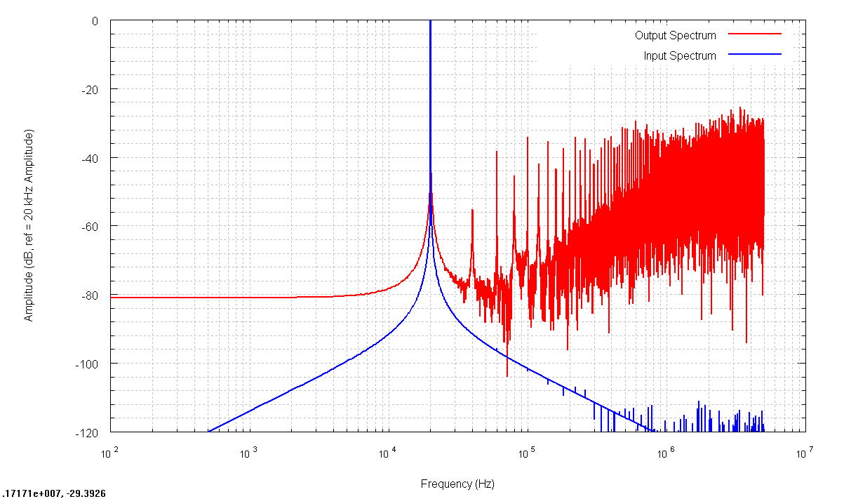
I did a simulation using a 10 MHz clock and a 20 kHz sine wave as input.
The input and output spectrums look like this:

That is way too much harmonic distortion, so there's an error somewhere. I'm also not sure why the skirt on the left side doesn't drop off for the output.
_________________
Software and Hardware Design |
|
|
Back to top
|
|
 |
jksuperstar

Joined: Aug 20, 2004
Posts: 2503
Location: Denver
Audio files: 1
G2 patch files: 18
|
 Posted: Fri Nov 13, 2009 8:38 am Post subject: Posted: Fri Nov 13, 2009 8:38 am Post subject:
|
  |
|
Hey, just for code clarity (which also helps find bugs), non-blocking assignments for combinational logic isn't a good idea. It could create a latch in many cases.
Try changing all of the :
reg x;
always@(*) x <= y;
to:
wire x;
x = y;
The (x ? y : z) conditional statements work for assign/wires also. |
|
|
Back to top
|
|
 |
jksuperstar

Joined: Aug 20, 2004
Posts: 2503
Location: Denver
Audio files: 1
G2 patch files: 18
|
 Posted: Fri Nov 13, 2009 8:47 am Post subject: Posted: Fri Nov 13, 2009 8:47 am Post subject:
|
  |
|
Looks pretty good though! I would try to fix that dc bias before the rest of the harminc distortion.
Since you are using non-blocking assignments, all of those "regs" that are defined won't be updated until the last thing before the end of the simulation tick, and they all happen at once. So, although it seems like the data flows through quant > quant_nef > FB etc. just as combinational logic, it might not be happening exactly how you would like it to be. That depends on the simulation timescale (for your frequencies `timescale 1ns/1ns should be fine). |
|
|
Back to top
|
|
 |
skrasms
Joined: Feb 21, 2008
Posts: 121
Location: Portland, OR
|
 Posted: Fri Nov 13, 2009 9:01 pm Post subject: Posted: Fri Nov 13, 2009 9:01 pm Post subject:
|
  |
|
| jksuperstar wrote: | Hey, just for code clarity (which also helps find bugs), non-blocking assignments for combinational logic isn't a good idea. It could create a latch in many cases.
Try changing all of the :
reg x;
always@(*) x <= y;
to:
wire x;
x = y;
The (x ? y : z) conditional statements work for assign/wires also. |
Thanks, I'll try that.
_________________
Software and Hardware Design |
|
|
Back to top
|
|
 |
skrasms
Joined: Feb 21, 2008
Posts: 121
Location: Portland, OR
|
 Posted: Fri Nov 13, 2009 11:13 pm Post subject: Posted: Fri Nov 13, 2009 11:13 pm Post subject:
|
  |
|
Today's lesson: LIMIT THE FEEDBACK
As the input wave gets near the extreme ranges of the converter, the feedback has a tendency to go off into the weeds and make bad things happen. It was even worse with a 1 kHz tone, but the solution was just to stick a limiter inline with the feedback. This is recommended in "Principles of Digital Audio," but it doesn't give a specific value. I set it to about 60% of full scale, and the majority of the noise/distortion faded out.
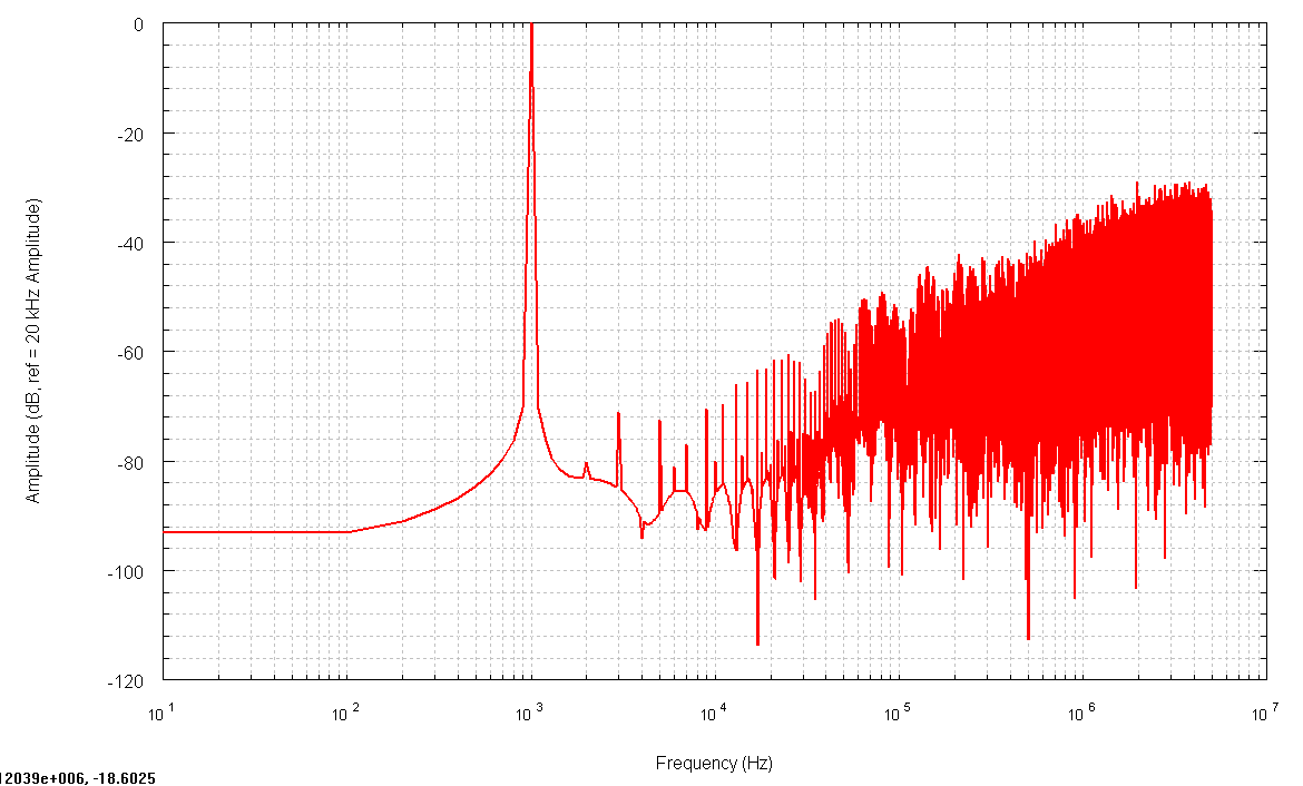
Here is the new output spectrum for a 1 kHz full-scale sine wave input:

There is still some distortion, but it is much better than before. I also haven't figured out the optimal limit range for the feedback.
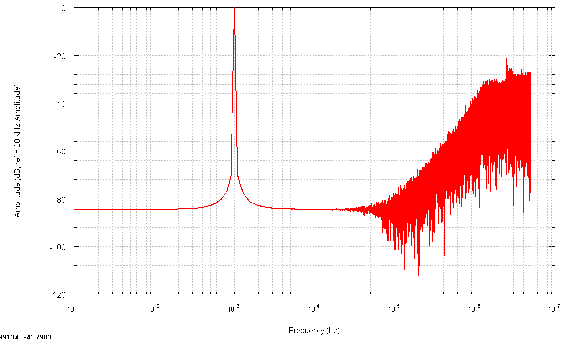
Dropping the input down by 6dB clears out the distortion completely:

I'm still not sure why the low frequency noise floor doesn't look better. From what I understand of the the theory, the noise should get lower and lower until it spikes at DC due to a natural offset created by the noise shaping process. On the other hand, the input data is only 16 bits, which is 96 dB dynamic range at best. The flat bottom is about -93 dB.
Edit: The amplitudes on the graphs are relative to the 1 kHz amplitude now, not 20 kHz.
The current stats are 185 logic elements and a 56.61 MHz max clock frequency on a Cyclone I. There is probably a more optimal way to do feedback limiting.
_________________
Software and Hardware Design |
|
|
Back to top
|
|
 |
|

