| Author |
Message |
funkyfarm

Joined: Jan 21, 2007
Posts: 583
Location: France
Audio files: 3
|
 Posted: Mon Dec 22, 2008 1:23 pm Post subject: Posted: Mon Dec 22, 2008 1:23 pm Post subject:
|
  |
|
sorry, i meant, assuming this 208 pseudo random thing to be driven by a VC-CLOCK (-10v into any vco), if you use the same signal (1V/oct, velocity...) for controlling both clock rate and Portamento/ 218 slew cv input, you have correlation between speed and slew.
sounds are sharper as rythm increases. |
|
|
Back to top
|
|
 |
funkyfarm
Joined: Jan 21, 2007
Posts: 583
Location: France
Audio files: 3
|
| Posted: Fri Mar 13, 2009 5:42 pm Post subject:
|
|
|
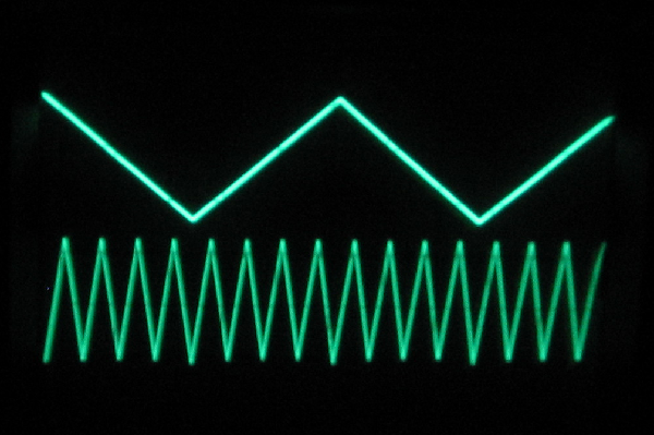
Here's what i mean (the fx is a little excessive) :
208 218 lfo saw control sample on http://sslstudiodesign.free.fr/218/
A descending ramp (saw lfo) controls both clock rate (wogglebug NE555) and CV IN on 218 slew.
First 208 output is processed trough this latter.
There is four sequences, i've cut control for 218 on the last. (ie all notes are fully slewed even at high clock rate)
I'm sure you could get cool patches with one or two (oncoming) Dunsel circuits here...
------------------------------------------------------------------------
208 outputs have a big big range ; it can be too much if you processed them via reversible attenuator (half curse) or use them for VCO.
I've put two voltage dividers (for 5V or so) on the two first outputs.
The two last are used for buchla (292 cv in, vactrol panner/xfader...)
Thank you for these pcb vtl5c3  |
|
|
Back to top
|
|
|
vtl5c3
Joined: Sep 08, 2006
Posts: 425
Location: PDX
Audio files: 13
|
| Posted: Sat Mar 14, 2009 7:50 pm Post subject:
|
|
|
Hi FUnky,
What is the Dunsel circuit?
Vtl.5c3 |
|
|
Back to top
|
|
|
Photon

Joined: Mar 22, 2005
Posts: 363
Location: Boston
Audio files: 1
|
|
|
Back to top
|
|
|
funkyfarm
Joined: Jan 21, 2007
Posts: 583
Location: France
Audio files: 3
|
| Posted: Sun Mar 15, 2009 10:10 am Post subject:
|
|
|
| you can get the positive part of any signal on a socket, and the negative part on another separate output socket (with no 0,7v drop...) |
|
|
Back to top
|
|
|
Funky40
Joined: Sep 24, 2005
Posts: 875
Location: Swiss
Audio files: 1
G2 patch files: 5
|
| Posted: Sun Mar 15, 2009 12:22 pm Post subject:
|
|
|
wow, i wish to have such a board,
what's missed is -A +5V,
has anybody n advice how to do this
ahh ok, i think i just have to come with +A instead of -A for the offset block, right ? ( see A+5 schematic top right ) |
|
|
Back to top
|
|
|
funkyfarm
Joined: Jan 21, 2007
Posts: 583
Location: France
Audio files: 3
|
| Posted: Sun Mar 15, 2009 1:17 pm Post subject:
|
|
|
yes !
A-5 = - (-A+5) = -(-A)-5
A+5 = - (-A-5) = -(-A)+5 |
|
|
Back to top
|
|
|
Scott Stites
Janitor


Joined: Dec 23, 2005
Posts: 4127
Location: Mount Hope, KS USA
Audio files: 96
|
|
|
Back to top
|
|
|
Tasmanian Alkaloid

Joined: Jun 29, 2008
Posts: 116
Location: Isle De Mort
|
| Posted: Sun Mar 15, 2009 10:47 pm Post subject:
|
|
|
Hi Romeo,
i'm planning to build 2 of these, but as i wrote up a parts list, i was unsure what 'FB' stands for (on the parts layout pdf). |
|
|
Back to top
|
|
|
numbertalk

Joined: May 05, 2008
Posts: 992
Location: Austin, TX
Audio files: 5
|
| Posted: Mon Mar 16, 2009 6:25 am Post subject:
|
|
|
| Tasmanian Alkaloid wrote: | Hi Romeo,
i'm planning to build 2 of these, but as i wrote up a parts list, i was unsure what 'FB' stands for (on the parts layout pdf). |
Ferrite Bead? |
|
|
Back to top
|
|
|
vtl5c3
Joined: Sep 08, 2006
Posts: 425
Location: PDX
Audio files: 13
|
| Posted: Mon Mar 16, 2009 8:21 am Post subject:
|
|
|
Yep. Ferrite Bead.
| numbertalk wrote: | | Tasmanian Alkaloid wrote: | Hi Romeo,
i'm planning to build 2 of these, but as i wrote up a parts list, i was unsure what 'FB' stands for (on the parts layout pdf). |
Ferrite Bead? |
|
|
|
Back to top
|
|
|
Tasmanian Alkaloid
Joined: Jun 29, 2008
Posts: 116
Location: Isle De Mort
|
| Posted: Mon Mar 16, 2009 7:44 pm Post subject:
|
|
|
| Thanks guys! |
|
|
Back to top
|
|
|
funkyfarm
Joined: Jan 21, 2007
Posts: 583
Location: France
Audio files: 3
|
| Posted: Wed Mar 18, 2009 4:51 pm Post subject:
|
|
|
| Scott Stites wrote: | | Quote: | | you can get the positive part of any signal on a socket, and the negative part on another separate output socket (with no 0,7v drop...) |
What you've just described is an ideal diode circuit. This is an exceedingly useful device for synth circuit design. If anyone hasn't already, be sure to check out Jim Patchell's write-up on it here:
http://www.uni-bonn.de/~uzs159/diode_tutorial/index.html
|
That's it ! IDEAL diode with no voltage drop.
I've build Patchell's too, with a -VBreak pot ; but i can remember outputs need to be buffered for multiple use.
Or maybe my two LED drivers need to be buffered...
The Dunsel module also have a FWR from these two outputs !?
Don't think about its use already...
 |
|
|
Back to top
|
|
|
LetterBeacon
Joined: Mar 18, 2008
Posts: 454
Location: London, UK
|
| Posted: Tue Jun 30, 2009 7:34 am Post subject:
|
|
|
| What type of capacitors would be appropriate for this circuit? I was planning on just using ceramics throughout as I have a lot of 0.1uF ceramics lying around. That should be fine, shouldn't it? |
|
|
Back to top
|
|
|
vtl5c3
Joined: Sep 08, 2006
Posts: 425
Location: PDX
Audio files: 13
|
| Posted: Tue Jun 30, 2009 8:00 am Post subject:
|
|
|
Yep, ceramics should be fine. They're mostly there for supply decoupling, which ceramics do pretty well. The board has spots for 10uF caps at the supply inputs, but you can probably leave those out.
Romeo
| LetterBeacon wrote: | | What type of capacitors would be appropriate for this circuit? I was planning on just using ceramics throughout as I have a lot of 0.1uF ceramics lying around. That should be fine, shouldn't it? |
|
|
|
Back to top
|
|
|
LetterBeacon
Joined: Mar 18, 2008
Posts: 454
Location: London, UK
|
| Posted: Tue Jun 30, 2009 8:12 am Post subject:
|
|
|
| Great, thanks a lot! |
|
|
Back to top
|
|
|
Photon
Joined: Mar 22, 2005
Posts: 363
Location: Boston
Audio files: 1
|
| Posted: Sat Aug 08, 2009 6:35 am Post subject:
|
|
|

Finished this recently. The most fun per rack unit in my whole system. thanks Romeo, Scott, and of course Mr. B. |
|
|
Back to top
|
|
|
vtl5c3
Joined: Sep 08, 2006
Posts: 425
Location: PDX
Audio files: 13
|
| Posted: Sat Aug 08, 2009 9:50 am Post subject:
|
|
|
| Thanks for the photo. Makes me feel warm and fuzzy on the inside seeing that! |
|
|
Back to top
|
|
|
pcp2020

Joined: Dec 25, 2007
Posts: 40
Location: boston
|
| Posted: Sun Aug 09, 2009 2:07 pm Post subject:
|
|
|
| I noticed that Scotts schematic wants 15 volts. would this work on 12? |
|
|
Back to top
|
|
|
Photon
Joined: Mar 22, 2005
Posts: 363
Location: Boston
Audio files: 1
|
|
|
Back to top
|
|
|
davemoog
Joined: Feb 23, 2008
Posts: 52
Location: Vancouver
|
| Posted: Tue Nov 03, 2009 11:13 pm Post subject:
4015 locking up? |
|
|
Has anyone had problems with the 4015 locking up and then no random CVs are produced? Powering off then on again will restart.
Thanks Dave |
|
|
Back to top
|
|
|
fluxmonkey
Joined: Jun 24, 2005
Posts: 708
Location: cleve
|
| Posted: Tue Nov 17, 2009 11:22 am Post subject:
|
|
|
i have a couple extra boards coming from ExpressPCB... if anyone would like them at cost + postage please drop me a PM with your email address.
thx
bbob
_________________
www.fluxmonkey.com |
|
|
Back to top
|
|
|
jooks
Joined: Mar 18, 2009
Posts: 15
Location: sweden
|
| Posted: Tue Nov 17, 2009 2:08 pm Post subject:
|
|
|
| Quote: | | have a couple extra boards coming from ExpressPCB... if anyone would like them at cost + postage please drop me a PM with your email address. |
PM sent. |
|
|
Back to top
|
|
|
valis

Joined: Sep 16, 2008
Posts: 121
Location: Oregon, USA
Audio files: 6
|
| Posted: Thu Nov 19, 2009 9:23 pm Post subject:
|
|
|
| bbob wrote: | i have a couple extra boards coming from ExpressPCB... if anyone would like them at cost + postage please drop me a PM with your email address.
thx
bbob |
I sent you a PM yesterday.. |
|
|
Back to top
|
|
|
janvanvolt

Joined: Nov 24, 2005
Posts: 285
Location: Mainz, Germany
|
|
|
Back to top
|
|
|
|

 Forum index » DIY Hardware and Software