| Author |
Message |
fonik

Joined: Jun 07, 2006
Posts: 3950
Location: Germany
Audio files: 23
|
 Posted: Mon Oct 25, 2010 5:05 am Post subject: Posted: Mon Oct 25, 2010 5:05 am Post subject:
|
  |
|
hi folks,
i just wanted to let you all know that i did not ship any PCBs yet. it is just because i have been occupied by my daily job last week. nevertheless all your payments have been received thankfully. you e-m forum members show a valuable discipline and responsibility.
i will ship the PCBs this week and will inform you on that via paypal.
thank you.
_________________

cheers,
matthias
____________
Big Boss at fonitronik
Tech Buddy at Random*Source |
|
|
Back to top
|
|
 |
mono-poly

Joined: Jul 07, 2004
Posts: 937
Location: Rotterdam, Netherlands
Audio files: 2
|
| Posted: Mon Oct 25, 2010 6:35 am Post subject:
|
|
|
| fonik wrote: | | mono-poly wrote: | | Is this also coming as an euro module? |
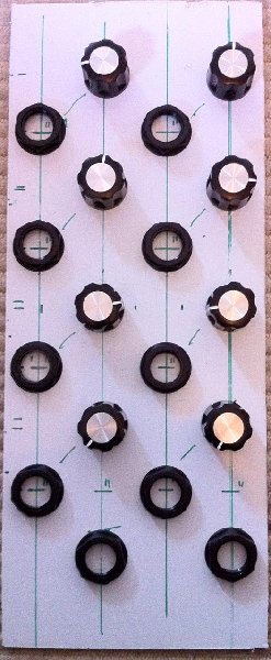
look this:
 |
Love a few of those  |
|
|
Back to top
|
|
|
Lbarros

Joined: Oct 27, 2010
Posts: 4
Location: Portugal
|
| Posted: Wed Oct 27, 2010 10:20 am Post subject:
|
|
|
well,one for me too please.
Thanks Matthias. |
|
|
Back to top
|
|
|
valis

Joined: Sep 16, 2008
Posts: 121
Location: Oregon, USA
Audio files: 6
|
| Posted: Thu Oct 28, 2010 12:30 am Post subject:
|
|
|
| This sounds like a fun and easy project. If you have any pcbs left please let me know as I'd like one. Thanks! |
|
|
Back to top
|
|
|
fonik
Joined: Jun 07, 2006
Posts: 3950
Location: Germany
Audio files: 23
|
|
|
Back to top
|
|
|
rosch

Joined: Oct 03, 2009
Posts: 164
Location: germany
|
| Posted: Thu Oct 28, 2010 4:08 am Post subject:
|
|
|
| mine arrived today! thank you very much!! |
|
|
Back to top
|
|
|
numbertalk

Joined: May 05, 2008
Posts: 992
Location: Austin, TX
Audio files: 5
|
| Posted: Thu Oct 28, 2010 5:58 am Post subject:
|
|
|
Hi Matthias,
How do you properly adjust the 2 trimmers? It looks like they're for minimizing the offset of the OTAs, right? What is the proper procedure though - feeding an LFO into the mod input, looking at the test point with a scope and adjusting the trimmer until the bleedthrough of the LFO signal is minimized there?
Very much looking forward to getting my board, thanks! |
|
|
Back to top
|
|
|
e-grad
Joined: Sep 12, 2008
Posts: 142
Location: Berlin
|
| Posted: Thu Oct 28, 2010 7:49 am Post subject:
|
|
|
Just have received mine. It's tiny! 
Thanks! |
|
|
Back to top
|
|
|
fonik
Joined: Jun 07, 2006
Posts: 3950
Location: Germany
Audio files: 23
|
| Posted: Thu Oct 28, 2010 9:13 am Post subject:
|
|
|
| numbertalk wrote: | | How do you properly adjust the 2 trimmers? It looks like they're for minimizing the offset of the OTAs, right? What is the proper procedure though - feeding an LFO into the mod input, looking at the test point with a scope and adjusting the trimmer until the bleedthrough of the LFO signal is minimized there? |
almost.
feed the input with an audio sine, and look at the testpoint to get the shape of the sine corrected.
i will look deeper into this on the weekend to come up with a good procedure, that could be implemented to the documentation then...
_________________
cheers,
matthias
____________
Big Boss at fonitronik
Tech Buddy at Random*Source |
|
|
Back to top
|
|
|
emdot_ambient
Joined: Nov 22, 2009
Posts: 667
Location: Frederick, MD
|
| Posted: Thu Oct 28, 2010 10:00 am Post subject:
|
|
|
| fonik wrote: | | ...feed the input with an audio sine... |
 I just read a post from someone in an old thread complaining about how most VCOs these days don't include sine waves. I just read a post from someone in an old thread complaining about how most VCOs these days don't include sine waves. |
|
|
Back to top
|
|
|
valis
Joined: Sep 16, 2008
Posts: 121
Location: Oregon, USA
Audio files: 6
|
| Posted: Thu Oct 28, 2010 10:13 am Post subject:
|
|
|
| Sorry if I'm a little dense but are these pcbs through-hole or SMT? |
|
|
Back to top
|
|
|
e-grad
Joined: Sep 12, 2008
Posts: 142
Location: Berlin
|
| Posted: Thu Oct 28, 2010 10:23 am Post subject:
|
|
|
| Through hole no SMT parts involved. |
|
|
Back to top
|
|
|
valis
Joined: Sep 16, 2008
Posts: 121
Location: Oregon, USA
Audio files: 6
|
| Posted: Thu Oct 28, 2010 11:26 am Post subject:
|
|
|
| Thanks! |
|
|
Back to top
|
|
|
a100user

Joined: Oct 28, 2003
Posts: 158
Location: UK
|
| Posted: Fri Oct 29, 2010 1:32 am Post subject:
|
|
|
Hi Matthias
Are you likely to be producing Euro front panels for this module?
Thanks
David
Last edited by a100user on Fri Oct 29, 2010 1:49 am; edited 1 time in total |
|
|
Back to top
|
|
|
LektroiD

Joined: Aug 23, 2008
Posts: 1019
Location: Scottish Borders
Audio files: 2
G2 patch files: 2
|
| Posted: Fri Oct 29, 2010 1:43 am Post subject:
|
|
|
I'm now wondering how to do a 5U for this, If I do standard MOTM 1U, I'll have nowhere to put the extra socket, and it seems a little wasteful to use a 2U panel just to accommodate 1 extra socket. I may have to use smaller rotary knobs and place the sockets next to each of those
Any other 5U guys out there building this?
_________________
LektroiD |
|
|
Back to top
|
|
|
fonik
Joined: Jun 07, 2006
Posts: 3950
Location: Germany
Audio files: 23
|
| Posted: Fri Oct 29, 2010 2:03 am Post subject:
|
|
|
| a100user wrote: | Hi Matthias
Are you likely to be producing Euro front panels for this module?
Thanks
David |
actually not.
_________________
cheers,
matthias
____________
Big Boss at fonitronik
Tech Buddy at Random*Source |
|
|
Back to top
|
|
|
a100user
Joined: Oct 28, 2003
Posts: 158
Location: UK
|
| Posted: Fri Oct 29, 2010 2:14 am Post subject:
|
|
|
OK thanks Matthias
David |
|
|
Back to top
|
|
|
magman
Joined: Feb 04, 2009
Posts: 363
Location: Liverpool, UK
|
| Posted: Fri Oct 29, 2010 7:35 am Post subject:
|
|
|
| LektroiD wrote: | I'm now wondering how to do a 5U for this, If I do standard MOTM 1U, I'll have nowhere to put the extra socket, and it seems a little wasteful to use a 2U panel just to accommodate 1 extra socket. I may have to use smaller rotary knobs and place the sockets next to each of those
Any other 5U guys out there building this? |
I've got 2 on the way, so I'm planning to squeeze 2 rows of 5 sockets on a 2U panel (You can just get away with this using Switchcraft jacks) for the both of them on one panel.
Regards
Magman |
|
|
Back to top
|
|
|
TekniK

Joined: Aug 10, 2008
Posts: 1059
|
| Posted: Fri Oct 29, 2010 8:36 am Post subject:
|
|
|
recieved mine,realy cute pcb's
10x Matt! |
|
|
Back to top
|
|
|
numbertalk
Joined: May 05, 2008
Posts: 992
Location: Austin, TX
Audio files: 5
|
| Posted: Fri Oct 29, 2010 8:37 am Post subject:
|
|
|
Thanks!
| fonik wrote: | | numbertalk wrote: | | How do you properly adjust the 2 trimmers? It looks like they're for minimizing the offset of the OTAs, right? What is the proper procedure though - feeding an LFO into the mod input, looking at the test point with a scope and adjusting the trimmer until the bleedthrough of the LFO signal is minimized there? |
almost.
feed the input with an audio sine, and look at the testpoint to get the shape of the sine corrected.
i will look deeper into this on the weekend to come up with a good procedure, that could be implemented to the documentation then... |
|
|
|
Back to top
|
|
|
LektroiD
Joined: Aug 23, 2008
Posts: 1019
Location: Scottish Borders
Audio files: 2
G2 patch files: 2
|
|
|
Back to top
|
|
|
magman
Joined: Feb 04, 2009
Posts: 363
Location: Liverpool, UK
|
| Posted: Fri Oct 29, 2010 3:36 pm Post subject:
|
|
|
Here's a first pass MOTM 2U Panel.
Regards
Magman
| Description: |
| 2U MOTM Panel in PDF Format |
|

Download |
| Filename: |
Ringmod 2U MOTM Panel.PDF |
| Filesize: |
176.67 KB |
| Downloaded: |
239 Time(s) |
| Description: |
| 2U MOTM Panel in FPD Format |
|
Download |
| Filename: |
Fonik 2U Ringmod.fpd |
| Filesize: |
2.79 KB |
| Downloaded: |
198 Time(s) |
|
|
|
Back to top
|
|
|
LektroiD
Joined: Aug 23, 2008
Posts: 1019
Location: Scottish Borders
Audio files: 2
G2 patch files: 2
|
| Posted: Sat Oct 30, 2010 7:05 am Post subject:
|
|
|
Boards arrived! Thanks Fonik.
Just wondering if there would be much degradation in sound if I used ceramic caps for C3, C4, C5, C6, C7, C8? Just that I've run out of 100n poly caps..
_________________
LektroiD |
|
|
Back to top
|
|
|
fonik
Joined: Jun 07, 2006
Posts: 3950
Location: Germany
Audio files: 23
|
| Posted: Sat Oct 30, 2010 3:17 pm Post subject:
|
|
|
| LektroiD wrote: | | Just wondering if there would be much degradation in sound if I used ceramic caps for C3, C4, C5, C6, C7, C8? Just that I've run out of 100n poly caps.. |
no. these are not part of the actual signal path, but just used to decouple the ICs from the power rails.
_________________
cheers,
matthias
____________
Big Boss at fonitronik
Tech Buddy at Random*Source |
|
|
Back to top
|
|
|
LektroiD
Joined: Aug 23, 2008
Posts: 1019
Location: Scottish Borders
Audio files: 2
G2 patch files: 2
|
| Posted: Sat Oct 30, 2010 5:15 pm Post subject:
|
|
|
| fonik wrote: | | LektroiD wrote: | | Just wondering if there would be much degradation in sound if I used ceramic caps for C3, C4, C5, C6, C7, C8? Just that I've run out of 100n poly caps.. |
no. these are not part of the actual signal path, but just used to decouple the ICs from the power rails. |
It's ok, I used ceramics at the PSU stage, and I found a couple of polyester film capacitors for the rest of the circuit. I didn't realise they were decoupling caps at the time, as I only just got your reply, and was impatient to build this, or I'd have just used ceramics throughout. Oh well, they're built now (not tested yet though).
_________________
LektroiD |
|
|
Back to top
|
|
|
|

 Forum index » DIY Hardware and Software » fonik's place