| Author |
Message |
jumunius
Joined: Apr 19, 2010
Posts: 346
Location: San Francisco, CA
Audio files: 13
|
 Posted: Wed Apr 06, 2011 3:37 pm Post subject:
CGS Gate-Trig Stripboard help? Posted: Wed Apr 06, 2011 3:37 pm Post subject:
CGS Gate-Trig Stripboard help? |
  |
|
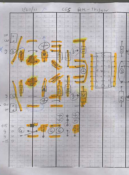
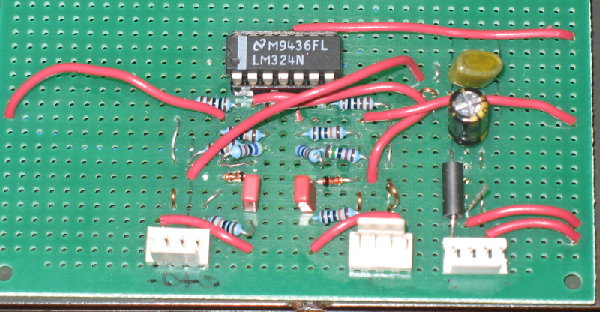
Hi, I'm testing my first ever stripboard project, the first half of a dual CGS Gate-Trigger converter, and I'm not having much luck. I wonder if anyone could offer advice. My rough layout on tripad and photos from my project are attached. Apologies for the density of the layout, which makes it hard to "read" with many components stacked atop one another.
Current situation:
I get nothing using the Gate out of an SH101 through the Gate-Trig converter (using either opamp 1 or opamp 2) into Trigger inputs of either the MPS or the Papareil DS8 (both work with a piezo or when directly connected to the SH101 Gate out).
I have approx 15v on pins 2, 4, and 6. I'm not convinced I have a working scope, so I'm only testing with a DVM.
Previously, I accidentally had connected Pin 2 of my LM 324 to ground, and left all of op-amp 1's circuit (in, out, ground, etc) unconnected to ground. I got erratic behavior, but generally found the note-off would activate the trigger. Now that I have "troubleshot" that problem, I get nothing from either note-on or note-off state.
I've tested a lot of the wiring for faults -- everything that is supposed to run to ground appears to now. Inputs and outputs appear to pass cleanly to their respective sections on the board.
Any ideas about what might be going on here would be appreciated.
| Description: |
| Stripboard/tripad layout. Notice that the topmost in/out header on my board one row above the "strip" as designed here, and none of the right side of the design is used, save for the ground connected to pin 11. |
|
| Filesize: |
279.66 KB |
| Viewed: |
266 Time(s) |
| This image has been reduced to fit the page. Click on it to enlarge. |
|
| Description: |
| Component side (3rd and 4th op-amps unused). |
|
| Filesize: |
215.14 KB |
| Viewed: |
265 Time(s) |
| This image has been reduced to fit the page. Click on it to enlarge. |
|
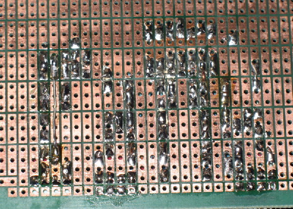
| Description: |
| Solder side of the board. (I reviewed with magnifying glass after this photo was taken, and cleaned between the pad to make sure there were no whiskers, etc -- didn't help) |
|
| Filesize: |
417.48 KB |
| Viewed: |
268 Time(s) |
| This image has been reduced to fit the page. Click on it to enlarge. |
|
|
|
|
Back to top
|
|
 |
andrewF

Joined: Dec 29, 2006
Posts: 1176
Location: australia
Audio files: 4
|
| Posted: Wed Apr 06, 2011 4:39 pm Post subject:
Re: CGS Gate-Trig Stripboard help? |
|
|
| jumunius wrote: |
I have approx 15v on pins 2, 4, and 6.
|
Pins 2 & 6 should have approx 2V on them. It will not work otherwise.
They should be connected together.
Is the 15k resistor connected from pins 2&6 to ground?
Is the 100k resistor connected from pins 2&6 to +V ?
These two resistors form a voltage divider, so pins 2&6 see 2V
(well... 1.956V).
When the input goes above 2V, the output will go high. |
|
|
Back to top
|
|
|
jumunius
Joined: Apr 19, 2010
Posts: 346
Location: San Francisco, CA
Audio files: 13
|
| Posted: Wed Apr 06, 2011 5:24 pm Post subject:
|
|
|
AHA, no the 15k was connected to +15 as well! It's amazing how no matter how many times I looked at the schematics, layout, etc, I did not notice that 15k should go to ground. 
Thanks for your input -- it works like a charm now! |
|
|
Back to top
|
|
|
|

 Forum index » DIY Hardware and Software » Ken Stone designs - CGS
