| Author |
Message |
echoer
Joined: Dec 10, 2009
Posts: 40
Location: lawrence, ks
|
 Posted: Wed Oct 05, 2011 5:59 pm Post subject:
MPS wiring diagram for the Bridechamber Panel Layout Posted: Wed Oct 05, 2011 5:59 pm Post subject:
MPS wiring diagram for the Bridechamber Panel Layout |
  |
|
Just getting ready to wire up my MPS. I've looked around and haven't seen a wiring diagram for the Bridechamber MPS Panel. The Bridechamber Panel is MOTM and 5U wide. Quite sexy if you're in to wide stuff. If you guys want I can make a drawing (hand drawn, analog baby) and scan it for us users.
You want/need?
I didn't put this in the MPS thread because after 28 pages of people ordering boards and troubleshooting it's getting a bit bloated.
_________________
- jason
freestatefx.com |
|
|
Back to top
|
|
 |
julianw

Joined: Jul 30, 2007
Posts: 78
Location: UK
|
| Posted: Thu Oct 06, 2011 3:26 pm Post subject:
|
|
|
Yes please post whatever you have.
I've got 2 stuffed pcbs & the Bridechamber panels.
Diagrams would be extremely helpful.
 |
|
|
Back to top
|
|
|
echoer
Joined: Dec 10, 2009
Posts: 40
Location: lawrence, ks
|
| Posted: Thu Oct 06, 2011 4:53 pm Post subject:
|
|
|
Glad to see that it will help.
Waiting on a few switches; no no no On/On/On switches in stock.
Once I got what I got so far verified I will scan and throw it up. Sometime next week.
_________________
- jason
freestatefx.com |
|
|
Back to top
|
|
|
jumunius
Joined: Apr 19, 2010
Posts: 346
Location: San Francisco, CA
Audio files: 13
|
| Posted: Sun Oct 09, 2011 1:02 am Post subject:
|
|
|
| echoer wrote: | | no no no On/On/On switches in stock. |
Why (why why) do you need one of those? Pretty sure there's no on-on-on switch required if you're using switching jacks. (Bugbrand's layout uses the On-On-On to switch off noise/impact cv when using external cv, which is easily done by a switching jack.) I didn't build the Bridechamber panel, per se, so correct me if I'm wrong.
And yes, I think people would appreciate the Bridechamber wiring doc, if only because it is probably more adherent to Thomas Henry's final design than Bugbrand's was, and thus will clarify some confusions like the one above. |
|
|
Back to top
|
|
|
echoer
Joined: Dec 10, 2009
Posts: 40
Location: lawrence, ks
|
| Posted: Sun Oct 09, 2011 4:31 pm Post subject:
|
|
|
Ahh... 
I was using Bugbrands layout as one of my references and he had them on his panel so I assumed I missed something and put them in my diagram as well. Since I am using switching jacks (N.C.) then it looks like they aren't necessary.
Thanks for the clarification. It looks like I can go ahead and finish it up then. Hopefully there won't be too many more bugaboos.
_________________
- jason
freestatefx.com |
|
|
Back to top
|
|
|
jumunius
Joined: Apr 19, 2010
Posts: 346
Location: San Francisco, CA
Audio files: 13
|
| Posted: Sun Oct 09, 2011 4:38 pm Post subject:
|
|
|
| echoer wrote: | | Ahh... |
No need to be embarrassed. I initially did the same thing, for one.  |
|
|
Back to top
|
|
|
echoer
Joined: Dec 10, 2009
Posts: 40
Location: lawrence, ks
|
| Posted: Mon Oct 10, 2011 12:20 pm Post subject:
|
|
|
Well something tells me we aren't the only two.
The hand drawn diagram is done and correct except for a couple switches. Unfortunately I used un-erasable colored pencils to make it easier to see which wire was which and now that copy is screwed. I'll just make the diagram in photoshop instead. ETA is this week.[/quote]
_________________
- jason
freestatefx.com |
|
|
Back to top
|
|
|
echoer
Joined: Dec 10, 2009
Posts: 40
Location: lawrence, ks
|
| Posted: Wed Oct 12, 2011 10:26 pm Post subject:
|
|
|
Got 'er done. Took a little while but I think it turned out pretty clean. If you have any questions about the diagram please ask.

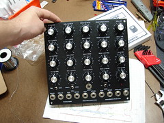

View is from the backside of the MPS Bridechamber Panel. Let me know if you catch any mistakes. It's in pencil so I can correct and re-scan in necessary.
I think this is a great module. I am anxious to fire it up alongside my MPC.
_________________
- jason
freestatefx.com |
|
|
Back to top
|
|
|
jumunius
Joined: Apr 19, 2010
Posts: 346
Location: San Francisco, CA
Audio files: 13
|
| Posted: Wed Oct 12, 2011 11:22 pm Post subject:
|
|
|
| echoer wrote: | | Got 'er done. Took a little while but I think it turned out pretty clean. If you have any questions about the diagram please ask. |
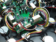
Nice looking doc! And really clean build too. I'm jealous.
After working a bit on mods I'm trying to get mine back up and running. (Noise is not back yet... hmmm.) So it's good timing.
I'm checking out your doc and the first thing I notice is the way you handle the Noise CV. Firstly, it goes into 13-1 on your diagram. 13-1, as far as I can tell, is unconnected. Did you attach a lead under the board? Secondly, you don't have any negative voltage protection there... from what I've read, you don't want negative voltages going into the LM13700 at the CV point (pins 1-6). Thoughts? |
|
|
Back to top
|
|
|
echoer
Joined: Dec 10, 2009
Posts: 40
Location: lawrence, ks
|
| Posted: Thu Oct 13, 2011 12:32 am Post subject:
|
|
|
| jumunius wrote: | | echoer wrote: | | Got 'er done. Took a little while but I think it turned out pretty clean. If you have any questions about the diagram please ask. |
Nice looking doc! And really clean build too. I'm jealous.
After working a bit on mods I'm trying to get mine back up and running. (Noise is not back yet... hmmm.) So it's good timing.
I'm checking out your doc and the first thing I notice is the way you handle the Noise CV. Firstly, it goes into 13-1 on your diagram. 13-1, as far as I can tell, is unconnected. Did you attach a lead under the board? Secondly, you don't have any negative voltage protection there... from what I've read, you don't want negative voltages going into the LM13700 at the CV point (pins 1-6). Thoughts? |
thanks. i am thinking on some mods myself. casperelectronics had some great ideas.
oh ya. i forgot to put the J13/1 "jumper note" in there. I put a jumper under the board between unused pin 1 of J13 and the junction of R16/Pin 6 of IC6. I don't know if i worded that last sentence properly.
bridge rectifier to prevent negative voltages at pins 1 & 16 of IC1?
_________________
- jason
freestatefx.com |
|
|
Back to top
|
|
|
jumunius
Joined: Apr 19, 2010
Posts: 346
Location: San Francisco, CA
Audio files: 13
|
| Posted: Thu Oct 13, 2011 12:56 am Post subject:
|
|
|
| echoer wrote: | oh ya. i forgot to put the J13/1 "jumper note" in there. I put a jumper under the board between unused pin 1 of J13 and the junction of R16/Pin 6 of IC6. I don't know if i worded that last sentence properly.
bridge rectifier to prevent negative voltages at pins 1 & 16 of IC1? |
R16 isn't anywhere near Pin 6 of IC6, but that's the right pin for a control voltage so it makes sense.
I must admit to being a bit confused about the negative voltage warning. I resuscitated my noise -- bad LM13700 -- but one thing I noticed is that the voltage applied to 1 and 16 of IC1 is generally negative. IC6b is an inverting amp being fed by +v. So maybe the problem would be + voltages at pin 1 and 16, which could be caused by negative voltages at Pin 6 of IC6.
As an aside, now that my noise is robust I realize that my shell and impact have become extremely weak. I can't win. |
|
|
Back to top
|
|
|
echoer
Joined: Dec 10, 2009
Posts: 40
Location: lawrence, ks
|
| Posted: Thu Oct 13, 2011 12:55 pm Post subject:
|
|
|
correction: R64 not R16. It was late last night 
_________________
- jason
freestatefx.com |
|
|
Back to top
|
|
|
Uncle Krunkus
Moderator

Joined: Jul 11, 2005
Posts: 4761
Location: Sydney, Australia
Audio files: 52
G2 patch files: 1
|
| Posted: Thu Oct 13, 2011 3:52 pm Post subject:
|
|
|
Keep in mind that Thomas never intended there to be any extra CV connections at all. It was an idea which came up, and I put some extra pads on the board, but Thomas was not happy about it, and it almost derailed the whole process.
Protecting the LM13700 from the wrong voltages properly would require a more complicated approach, and is the reason Thomas wanted to leave it as it is.
If you're having problems getting all three sections working well, my advice would be to forget about the 2 extra CVs completely until you have it all finished and tested. Then experiment if you really want, being aware that you may destroy some LM13700s in the process.
_________________
What makes a space ours, is what we put there, and what we do there. |
|
|
Back to top
|
|
|
jumunius
Joined: Apr 19, 2010
Posts: 346
Location: San Francisco, CA
Audio files: 13
|
| Posted: Thu Oct 13, 2011 4:13 pm Post subject:
|
|
|
| Uncle Krunkus wrote: | | If you're having problems getting all three sections working well, my advice would be to forget about the 2 extra CVs completely until you have it all finished and tested. Then experiment if you really want, being aware that you may destroy some LM13700s in the process. |
Thanks -- I actually had it all working. Not sure when I fried the LM13700, I hadn't done much modding yet, but who knows. Maybe the VCA's LM13700 got fried too, which might account for low output of the Impact and Shell?
I saw in the gargantuan original thread that you said you were working out a means to add a noise CV in. Did you ever get that working? I'm less interested in adding an Impact CV myself.
What I AM trying to do mainly is to add a 2nd percussive envelope generator that routes to Noise and Shell's Pitch and VCA (with a switch to route it to one or two of these circuits). This would be a shorter envelope, mainly to accentuate the impact portion of the sound in different ways (like be able to add a lot of pop to the beginning of the sound, even if the sound has a long decay.
However, I am a little hesitant about messing too much now with the LM13700s, since apparently they are sensitive to excessive current amongst other things. |
|
|
Back to top
|
|
|
Uncle Krunkus
Moderator
Joined: Jul 11, 2005
Posts: 4761
Location: Sydney, Australia
Audio files: 52
G2 patch files: 1
|
| Posted: Thu Oct 13, 2011 4:20 pm Post subject:
|
|
|
I don't know enough about the LM13700 to make that call.
+ve/-ve voltages could probably be stopped with a schottky diode to GND?
Apart from that, I would be only speculating, and it would still need to be tried and tested before you'd be 100% sure that ANY CV coming in would be safe.
_________________
What makes a space ours, is what we put there, and what we do there. |
|
|
Back to top
|
|
|
jumunius
Joined: Apr 19, 2010
Posts: 346
Location: San Francisco, CA
Audio files: 13
|
| Posted: Sat Oct 15, 2011 12:48 am Post subject:
|
|
|
| Uncle Krunkus wrote: | I don't know enough about the LM13700 to make that call.
+ve/-ve voltages could probably be stopped with a schottky diode to GND?
Apart from that, I would be only speculating, and it would still need to be tried and tested before you'd be 100% sure that ANY CV coming in would be safe. |
Ok, thanks, duly noted.
In case anyone is keeping track, I finally got 10 minutes to look at why my Shell and Impact were so weak -- bad wiring of course. (The MPS constituted my first try at using MTA headers, and even after redoing most of my early crimping, I still find errors.) Don't underestimate the wiring faults! Looking at my "handiwork" I was mostly surprised I had heard anything at all from them. |
|
|
Back to top
|
|
|
marvkaye
Joined: Mar 14, 2011
Posts: 225
Location: Fla
|
| Posted: Sat Oct 15, 2011 4:02 am Post subject:
|
|
|
| jumunius wrote: |
In case anyone is keeping track, I finally got 10 minutes to look at why my Shell and Impact were so weak -- bad wiring of course. (The MPS constituted my first try at using MTA headers, and even after redoing most of my early crimping, I still find errors.) Don't underestimate the wiring faults! Looking at my "handiwork" I was mostly surprised I had heard anything at all from them. |
How frustrating is that?!?  I can relate totally. I can relate totally.
In Scott Stite's excellent build docs for both the Appendage and the Klee Sequencer he stresses in boldface the importance of tinning the wires prior to crimping. And in another thread here somewhere I seem to remember another of our colleagues mentioning that he would solder and crimp, which is probably a great idea as well. Nothing wrong with a "belt & suspenders" approach, for sure.
The folks at Synthesizers.com use the AMP #6404412 connector, with obvious great success... the pins come already installed and use IDC (Insulation Displacement Contact) - "This is a technique that allows the insulation of the wire to be pierced while the wire is being inserted into the contact slot, providing an economical method of mass terminating wires." (That last part is quoted straight from their data sheet.)
Irrespective of all that, it's good to hear that you found the source of your volume problem. I've always been a sucker for happy endings.
<marv> |
|
|
Back to top
|
|
|
Uncle Krunkus
Moderator
Joined: Jul 11, 2005
Posts: 4761
Location: Sydney, Australia
Audio files: 52
G2 patch files: 1
|
| Posted: Sat Oct 15, 2011 1:52 pm Post subject:
|
|
|
That was probably me who said about soldering the crimp connectors. When I was laying out the Klee boards, Scott and I decided those molex type connectors were needed because of the sheer number of interconnections. But as we were prototyping the PCBs, I didn't want to have to troubleshoot crimps which had gone wrong. So I crimped and soldered every one of them. (there are heaps!)
Every connection was perfect from the word go, which made things heaps easier.
For a one off job with heaps of connections, why would you leave anything to chance?
Well, that's the way I see it anyway. 
_________________
What makes a space ours, is what we put there, and what we do there. |
|
|
Back to top
|
|
|
jumunius
Joined: Apr 19, 2010
Posts: 346
Location: San Francisco, CA
Audio files: 13
|
| Posted: Sat Oct 15, 2011 8:41 pm Post subject:
|
|
|
| marvkaye wrote: | | In Scott Stite's excellent build docs for both the Appendage and the Klee Sequencer he stresses in boldface the importance of tinning the wires prior to crimping. |
And when you forget to close one of said wires properly, or over-crimp another to the point of cutting the wire at the base of the crimp (seems to happen occasionally) you end up with two wires that don't work.
Ok, now that it works again, time to see if I can bust another LM13700. Only one spare left.... |
|
|
Back to top
|
|
|
TheAncientOne

Joined: Dec 26, 2006
Posts: 144
Location: United Kingdom
|
| Posted: Mon Oct 17, 2011 3:34 am Post subject:
|
|
|
| jumunius wrote: | | marvkaye wrote: | | In Scott Stite's excellent build docs for both the Appendage and the Klee Sequencer he stresses in boldface the importance of tinning the wires prior to crimping. |
And when you forget to close one of said wires properly, or over-crimp another to the point of cutting the wire at the base of the crimp (seems to happen occasionally) you end up with two wires that don't work.
Ok, now that it works again, time to see if I can bust another LM13700. Only one spare left.... |
Can I add that it's important to have both the right crimp tool, and the correct size of wire for the crimp you are fitting. A properly fitted crimp will not need tinning, but if your cable is a bit thin, then by all means tin it.
Crimp, and wire wrap were, (if I remember correctly), a result of US Admiralty research into broken connections on their ship board equipment. A wire to a solder joint has a discontinuity between the hard soldered section, and the flexible cores, supported by the insulation. Apparently vibration or fatigue cracking would occur at that point. Good crimps have a core crimp, and an insulation crimp, and form a very good connection, with effectively cold welding of the cores to the crimp, if done properly. If the wire is too thin, this won't happen.
I always do the 'Tug test' on mine - if it pulls free, Do It Again!
With a thinish cable, another option is to strip twice as much core as needed, then fold it back on itself to double the core thickness at the crimp.
A proper ratchet type crimp tool makes a lot of difference. Mine is from Rapid, their part number is 85-0262 Rapid Crimp Tool
The genuine Molex one is probably better, but I guess that will comer at a price.
As with soldering, practice makes perfect, my first efforts were terrible!
I'm not fond of the 'push down' type of IDC plus; in my years as a repair tech, they are one of the few types of IDC I have ever had to re-make. Properly machine fitted they seem to last well, but some examples, fitted with the simple hand push tool seem less reliable.
I don't think most synths are going to get the same pounding as Naval electronics though.
_________________
Mike |
|
|
Back to top
|
|
|
marvkaye
Joined: Mar 14, 2011
Posts: 225
Location: Fla
|
| Posted: Mon Oct 17, 2011 5:42 am Post subject:
|
|
|
In actuality, wire wrap was developed by Bell Labs. I used to work for them as a QA guy at Western Electric, way back in the days when ESS (electrronic switching systems) was taking over from step and crossbar switches, all of which used wire wrap extensively. One of our compatriots here builds amazing proto-boards using wire wrap exclusively... when he pipes in I'm sure he can point you at some of the photos of his work that he's shared here.
I agree wholeheartedly regarding crimping tools.... the ratcheting type will give you as close as you can get to a guaranteed proper crimp, assuming, of course, the tool is the correct one for both the pin and the wire. I do a lot of [experimental] aircraft wiring and we have a pretty interesting collection of crimpers to accommodate the many different types of pins we work with. I agree also with the warning about pricing... some of these tools run into the several hundreds of dollars, but you do get what you pay for.
Re: tug test.... Amen^2.
<marv> |
|
|
Back to top
|
|
|
echoer
Joined: Dec 10, 2009
Posts: 40
Location: lawrence, ks
|
| Posted: Mon Oct 17, 2011 12:31 pm Post subject:
|
|
|
I've had better results with crimps than the MTA type press connections. I solder the wire to the connector, regardless of whether it is initially crimped or pressed in place. The extra time is worth the peace of mind, especially if the synth/module is being gigged or shipped.
_________________
- jason
freestatefx.com |
|
|
Back to top
|
|
|
echoer
Joined: Dec 10, 2009
Posts: 40
Location: lawrence, ks
|
Posted: Mon Oct 17, 2011 12:38 pm Post subject:
 |
|
|
ThisWillNeverHappenInRealLife Entertainment pres. "Tug Test" a teacher/student romp feat. Shewanna Goallnight and Bob Throbbin.
_________________
- jason
freestatefx.com |
|
|
Back to top
|
|
|
jumunius
Joined: Apr 19, 2010
Posts: 346
Location: San Francisco, CA
Audio files: 13
|
| Posted: Mon Oct 17, 2011 8:28 pm Post subject:
|
|
|
| TheProf wrote: | | Good crimps have a core crimp, and an insulation crimp, and form a very good connection, with effectively cold welding of the cores to the crimp, if done properly. |
Good points, all of them. And the first time I made my MPS headers, I didn't realize there was a core crimp and an insulation crimp -- I did 2 core crimps. You can imagine that the result was not so sturdy when tugged around during the wiring of the panel. And yeah, I always do a tug test, but in this case half the time the crimps slipped out (this is before I discovered soldering the crimps). Crimping to the insulation is key, but aside from the Bass++ instruction manual I have yet to find any clear explanation of this.
| Quote: |
Can I add that it's important to have both the right crimp tool, and the correct size of wire for the crimp you are fitting. A properly fitted crimp will not need tinning, but if your cable is a bit thin, then by all means tin it.
|
Looks like mine except the ratcheting. I'll have to investigate. Thanks for the link -- the price is right!
| Quote: | I'm not fond of the 'push down' type of IDC plus; in my years as a repair tech, they are one of the few types of IDC I have ever had to re-make. Properly machine fitted they seem to last well, but some examples, fitted with the simple hand push tool seem less reliable.
|
As someone says below, I think these push-down types are pretty decent if you solder the result with a thin solder tip. I got that tip from modularsynthesis.com / Dave Brown. Works well. Only downside is it doesn't take well to unsoldering and resoldering, so make sure you don't need to swap out the wires. The molex style discussed above is pretty easy to undo when you realize you've made an error.
-Jim |
|
|
Back to top
|
|
|
TheAncientOne
Joined: Dec 26, 2006
Posts: 144
Location: United Kingdom
|
| Posted: Tue Oct 18, 2011 6:09 am Post subject:
|
|
|
| marvkaye wrote: | In actuality, wire wrap was developed by Bell Labs. I used to work for them as a QA guy at Western Electric, way back in the days when ESS (electrronic switching systems) was taking over from step and crossbar switches, all of which used wire wrap extensively. One of our compatriots here builds amazing proto-boards using wire wrap exclusively... when he pipes in I'm sure he can point you at some of the photos of his work that he's shared here.
<marv> |
Thanks for the correction. I think we all owe Bell Labs a major debt, a serious fraction of electronics innovation came from there; Claude Shannon, Unix, 'C', to mention but a few. All seems part of a lost golden age now.
I did a lot of wire wrap work in the 80's, wiring prototype ECL boards for an IRCAM designs, and loads of smaller stuff. I still use it myself today, though I tend to keep it more for digital work. It's kind of relaxing to do, a bit like my Mom and her needlepoint. When I get my 'paradoxical sound generator done, I'll post a pic. In the 80's I wrote my own netlist sorter that ran on my first ever computer: a Hewlett-Packard HP85, (for an inflation corrected version of the price I could have a whole studio worth of gear nowadays!), and I spent many an evening following my 32 column blue printout lists.
If anyone knows of a good cheap source for the 'Tefzel' wore that will work in my 'Strip 'n Wrap' bit, (the ordinary 'Kynar' has problems, I'd be very happy.
@Echoer - 'Strip 'n Wrap' might be another film title for you....
_________________
Mike |
|
|
Back to top
|
|
|
|

 Forum index » DIY Hardware and Software » Thomas Henry designs
