| Author |
Message |
KK303
Joined: Feb 13, 2012
Posts: 11
Location: UK
|
 Posted: Thu May 24, 2012 5:25 am Post subject:
Quick question! Switching sequencer!! Posted: Thu May 24, 2012 5:25 am Post subject:
Quick question! Switching sequencer!! |
  |
|
Hi! Quick question!!
For a long time I've been trying to build this 8 step sequencer with the 4017 and haven't really been satisifed with the results driving a 555 from it. I am now very happy with the sound of a 40106, and I had an idea whilst connecting four oscillator outputs to a rotary switch and switching between the outputs that the sequencer really ought to be able to work with this principle. Struggled for a while until coming across a 4066 chip in something I bought. Intrigued I immediately checked the datasheet and lo and behold it looks like the answer to my sequencer trouble. Has anyone tried this, a quick mock up in circuit wizard seems to suggest I could build a 40106 sequencer with 2x40106, 2x4066, have my eight pots controlling the frequency of 8 different oscillators off the 40106, and use a 9th osc as the clock for the 4017, have the 8 outputs of the 4017 turning on each switch on the 4066 and hopefully, very smooth sequencing between multiple oscillators from the 40106's with fine tuning on each. Does it sound possible, am I thinking along the right lines? I have heard there can be noticable pops when switching with a 4066, would this occur? I do realise using 8 different oscillators for a sequencer is a bit overkill, but given how easy it is to get a nice square wave from the 40106 for pennies it seems a fair enough trade off....I'm also thinking that a 4040 on the end of the chain (in parallel?) could generate a sub oscillator (or two) along with the sequence....for a real self cotained bass line/lead generator...theres always the trick of driving one 40106 osc from another with a diode in reverse (i think?) for some fake-filterish sounds...maybe I could use 16 oscillators!?! I don't havea penny to my name till pay day so until I can buy a 4066 (which will inevitably mean buying new pots, box, knobs, wire, solder, yada yada!!!) I just have this idea kiling my mind, would be great to hear if anyone has tried same, till now I was never able to find anyone doing switching like this?? |
|
|
Back to top
|
|
 |
JingleJoe

Joined: Nov 10, 2011
Posts: 878
Location: Lancashire, England
Audio files: 14
|
| Posted: Thu May 24, 2012 7:44 am Post subject:
|
|
|
Honestly I only read half your post but I think I have a good idea of what you're trying to do, let me read the rest, yeah you are doing how I thought you were. It's not really how other sequencers work.
While your idea is good, unless you want 8 different tracks or something I wouldn't go down that route.
I can save you alot of time and money and everything acctually with some tips and my latest design, yours for just 9,999,9,995 only joking 
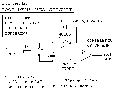
Other sequencers switch in a series of control voltages to one VCO, thus allowing you to have only one oscillator. I'll attach a schematic for my VCO, I have used it in loads of things very successfully. You could even use the CV input of a 555 timer if you don't mind about pulse width variation.
The way I would do this with a 4017 is to connect all the outputs from the 4017 to potentiometers wired up as voltage dividers (while we are on the subject, isn't the 4017 ten outputs? Why limit yourself to 8? use all ten!  ). ).
Then combine them with diodes. I suppose you could passively mix them...
Just remembered this! there you go, read that, it should answer alot of questions for you
I'll be back with that vco circuit in a bit.
_________________
As a mad scientist I am ruled by the dictum of science: "I could be wrong about this but lets find out"
Green Dungeon Alchemist Laboratories |
|
|
Back to top
|
|
|
DGTom

Joined: Dec 08, 2008
Posts: 211
Location: Adelaide
Audio files: 3
G2 patch files: 1
|
| Posted: Thu May 24, 2012 7:47 am Post subject:
|
|
|
It'll work. There will be clicks & pops but with squarewaves, odds are you will not hear them. It's a roundabout way to do it however.
Take a look at this page;
http://milkcrate.com.au/_other/sea-moss/
this drawing in particular;
http://milkcrate.com.au/_other/sea-moss/04_seq.gif
replace the 22Ks with 100K pots & you have the device you have described. 1 x 40106, 1 x 4051, 1 x 4040. Alot easier than building 8 seperate oscillators & the basic concept is very easy to expand on.
Add another 4051 & do 2 voices, make a little patchbay so that you can reassign the 4040 outputs to the 4051 control inputs.
Or try it a differant way; use the 4051 to switch capacitors & drive the 4040 at audio rates - you can make really nice 'filter' sounds this way |
|
|
Back to top
|
|
|
KK303
Joined: Feb 13, 2012
Posts: 11
Location: UK
|
| Posted: Thu May 24, 2012 8:03 am Post subject:
|
|
|
Aha...yes I have come across this circuit before....I think I see what you are saying. I just checked my local Maplin, they have 2 4051's and 1 4066, so i will pick those up and give this a spin tonight, it looks like the 4051 approach is really what i want tho! Thanks!!
Jinglejoe, yes I've built the baby8 in this manner before, but I was never happy with the sound it produced in the 555, it was a bit wimpy, this pulse width changing being offputting. Although I have had problems using voltage dividers....when i had my pots wired like this, I would find that an adjustment on one pot could change the resistance on another step, eventually leaving little room to sweep on the last step. When i just used it as a variable resistor with no ground, it worked ok, but I had problems when trying to use LED's...maybe theres something I am missing. On the getlofi site there was some transistor array introduced for some reason (to help with grounding?), but in the comments someone eventually proves with a spice simulation that it wasn't doing what they thought it was doing...although the link to that simulation is now dead.
If you have a better VCO than a standard 555 I would love to see it though!!!  Cheers!!! Cheers!!! |
|
|
Back to top
|
|
|
JingleJoe
Joined: Nov 10, 2011
Posts: 878
Location: Lancashire, England
Audio files: 14
|
|
|
Back to top
|
|
|
DGTom
Joined: Dec 08, 2008
Posts: 211
Location: Adelaide
Audio files: 3
G2 patch files: 1
|
| Posted: Thu May 24, 2012 8:28 am Post subject:
|
|
|
If its working / built right a baby 8 shouldn't have any interaction between pots.
Also, if you go the 4051 route don't hook up the pots exactly like the resistors in the sea moss drawing.
Wire them so the output pin of the 40106 goes to the same lug of each of the 8 pots, then wire the next door lug of each pot to each 4051 input - you want them in parallel not series. Its alot easier than messing with VCOs (for now!) & will sound the same as a 40106 wired up with a single pot.
Def. get both 4051s if you do, I think the best next step is to hook the clock oscillator up just like the voice, that way you have another row of pots to control the length of each note in the sequence. Bassline heaven! |
|
|
Back to top
|
|
|
JingleJoe
Joined: Nov 10, 2011
Posts: 878
Location: Lancashire, England
Audio files: 14
|
| Posted: Thu May 24, 2012 8:37 am Post subject:
|
|
|
In addition to what DGtom says, it sounds like you have wired your pots up wrong in your baby 8 sequencer.
_________________
As a mad scientist I am ruled by the dictum of science: "I could be wrong about this but lets find out"
Green Dungeon Alchemist Laboratories |
|
|
Back to top
|
|
|
nathanxl
Joined: Apr 24, 2012
Posts: 77
Location: Wa
|
| Posted: Fri May 25, 2012 4:53 am Post subject:
|
|
|
| DGTom wrote: | | Wire them so the output pin of the 40106 goes to the same lug of each of the 8 pots, then wire the next door lug of each pot to each 4051 input - you want them in parallel not series. |
Im trying this, looks like where Im at currently too.
Bit difficult for me(noob) to decipher. Any schematic update on the original sea-moss circuit design for me and my small brain to gander at??
Interested in this.
Thanks
N |
|
|
Back to top
|
|
|
DGTom
Joined: Dec 08, 2008
Posts: 211
Location: Adelaide
Audio files: 3
G2 patch files: 1
|
|
|
Back to top
|
|
|
DGTom
Joined: Dec 08, 2008
Posts: 211
Location: Adelaide
Audio files: 3
G2 patch files: 1
|
| Posted: Fri May 25, 2012 5:41 am Post subject:
|
|
|
oh yeah, if you want LEDs to tel you which step you are on, use a 4051, tie the comman pin (#3) to +ve via a resistor then wire up 8 leds to the outputs.
& experiment with the A/B/C inputs on the 4051 to make goofy sequences, just make sure if you do use the variable clock method to tie the 2 4051s address bits together. . . or not 
for example, if you use Q4, Q5 & Q6 to control the clock 4051 then the 8 step sequence will play at the same speed twice before it changes, good fun!
Edit; tap the output of the top left gate with a diode or resistor for the output, sorry. . . kinda forgot the important bit  |
|
|
Back to top
|
|
|
|

 Forum index » DIY Hardware and Software » Lunettas - circuits inspired by Stanley Lunetta