| Author |
Message |
regularjackson
Joined: Apr 12, 2012
Posts: 17
Location: Canada
|
 Posted: Sun Jun 24, 2012 1:43 pm Post subject:
Another lunetta psu thread Posted: Sun Jun 24, 2012 1:43 pm Post subject:
Another lunetta psu thread |
  |
|
| I know this has been discussed before, but I couldn't find a thread that really helped me. Basically I'm building a lunetta system right now and I really don't want to use batteries. Just looking for a basic way to plug this in to the wall if anyone can help me out. Thanks. |
|
|
Back to top
|
|
 |
Psyingo

Joined: Jun 11, 2009
Posts: 248
Location: Canada
|
 Posted: Sun Jun 24, 2012 5:51 pm Post subject: Posted: Sun Jun 24, 2012 5:51 pm Post subject:
|
  |
|

here is a quick schematic i drew up.
as stated in the schematic, the 78xx is a voltage regulator IC. The xx designates the desired output voltage, 7812 being a 12v regulator.
You will want to have a few volts higher of an input to the regulator so it can perform its regulating magic.
On each CMOS chip you should have a 100nF decoupling cap between the +v and gnd pins; as close as possible to those pins.
The diode is there to avoid negative voltage being applied to the circuit. |
|
|
Back to top
|
|
 |
regularjackson
Joined: Apr 12, 2012
Posts: 17
Location: Canada
|
 Posted: Sun Jun 24, 2012 6:05 pm Post subject: Posted: Sun Jun 24, 2012 6:05 pm Post subject:
|
  |
|
| Hey thanks, one question, what is JP1? |
|
|
Back to top
|
|
 |
Psyingo

Joined: Jun 11, 2009
Posts: 248
Location: Canada
|
 Posted: Sun Jun 24, 2012 6:06 pm Post subject: Posted: Sun Jun 24, 2012 6:06 pm Post subject:
|
  |
|
oh sorry, underneath Jp1 it says +V, but its not that clear.
Jp1 is the regulated voltage output. |
|
|
Back to top
|
|
 |
regularjackson
Joined: Apr 12, 2012
Posts: 17
Location: Canada
|
 Posted: Sun Jun 24, 2012 6:14 pm Post subject: Posted: Sun Jun 24, 2012 6:14 pm Post subject:
|
  |
|
| oh yeah, duh. I didn't sleep enough last night. Thanks! |
|
|
Back to top
|
|
 |
regularjackson
Joined: Apr 12, 2012
Posts: 17
Location: Canada
|
 Posted: Sun Jun 24, 2012 6:22 pm Post subject: Posted: Sun Jun 24, 2012 6:22 pm Post subject:
|
  |
|
| one other question I have pertaining to this is how to hook up a dc power jack for the wall wart? I don't know which terminals to hook up on the jack to what. I've searched around but I haven't been able to figure it out. Thanks. |
|
|
Back to top
|
|
 |
Psyingo

Joined: Jun 11, 2009
Posts: 248
Location: Canada
|
 Posted: Sun Jun 24, 2012 6:25 pm Post subject: Posted: Sun Jun 24, 2012 6:25 pm Post subject:
|
  |
|
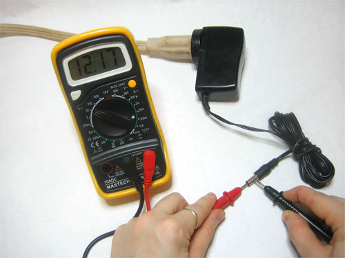
usually on the wall wart it will specify if the inside is positive or negative with a little graphic... like so...

but failing that it isn't marked, you can just hook it up to a multimeter to figure out which is positive.
...like so...
 |
|
|
Back to top
|
|
 |
attdestroyers

Joined: Mar 29, 2012
Posts: 47
Location: Malvern, Ohio
|
 Posted: Sun Jun 24, 2012 8:28 pm Post subject: Posted: Sun Jun 24, 2012 8:28 pm Post subject:
|
  |
|
I used this same exact setup using the 7805 for my lunetta. But, I figured the decoupling caps weren't necessary on each module since this regulated power supply is decoupled already. Bad idea? My lunetta runs great with this. Think I'll have problems in the future?
I was also unsure what amperage my power supply should be. I used a 2A wall wart. Seems to work good. |
|
|
Back to top
|
|
 |
Psyingo

Joined: Jun 11, 2009
Posts: 248
Location: Canada
|
 Posted: Sun Jun 24, 2012 8:34 pm Post subject: Posted: Sun Jun 24, 2012 8:34 pm Post subject:
|
  |
|
well in my video synth, for example, i didn't decouple at first.. when i had everything assembled together and was testing things everything was very noisey, with very visible distortions, lines and noise on the picture... i was scratching my head for a bit. someone suggested i decouple EVERY chip and i thought 'that cant make that much of a difference...' boy was i wrong. it cleaned everything up perfectly. the image was so crisp and clean!
another example is on my drum machine... again i didnt decouple and i got tons of bleed into the drum voices from the cymbal voices... decoupled all the chips and it was gone.
DECOUPLE ALL THE THINGS |
|
|
Back to top
|
|
 |
-minus-
Joined: Oct 26, 2008
Posts: 787
Audio files: 13
|
 Posted: Mon Jun 25, 2012 5:08 am Post subject: Posted: Mon Jun 25, 2012 5:08 am Post subject:
|
  |
|
Nice clear images and explanation on the psu. Looks like something you'd see in a really good book!
Yeah, I've been putting the caps on the chips for some time now. So you need them on the - pin as well? I have seen this done sometimes but haven't bothered  |
|
|
Back to top
|
|
 |
attdestroyers

Joined: Mar 29, 2012
Posts: 47
Location: Malvern, Ohio
|
 Posted: Mon Jun 25, 2012 5:48 pm Post subject: Posted: Mon Jun 25, 2012 5:48 pm Post subject:
|
  |
|
| ok, will do. It'll be interesting to hear how much difference it makes[/quote] |
|
|
Back to top
|
|
 |
|

