Tony Deff
Joined: May 25, 2008
Posts: 51
Location: Suffolk, UK
|
 Posted: Sun Aug 19, 2012 8:23 am Post subject:
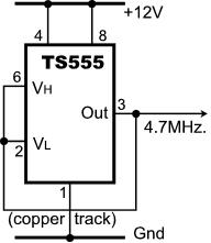
Ultra-Simple H.F. Test Oscillator Posted: Sun Aug 19, 2012 8:23 am Post subject:
Ultra-Simple H.F. Test Oscillator |
  |
|
(This posting is undergoing major editing)
You (more than) sometimes find that the timing of your 7555 is not quite as you'd expected, and by more than a trifle.
Frequently, you are told that this because of your component tolerances, yet you may look at your 2% resistor and 10% capacitor and wonder. What you are seldom told is that the 555 has its tolerances too, especially in its built-in resistor chain.
Resistors inside semiconductor networks are notoriously imprecise, but they are supposed to match each other closely, and obtaining a ratio of 2/3 supply at pin 5 is what it's all about. In National Semiconductor's original LM555, this is formed by a chain of three nominal 5K resistors (in the 7555, these are 100K and in the TS555, 200K).
The LM555's spec. sheet details the accuracy of these resistors in a curiously indirect way: it details the Control Voltage Level (Electrical Characteristics) min., typ. and max. for a supply of 15V and 5V. For the LM555C (Commercial variant) at 15V, this is 9,10 or 11V, i.e. ±10%.
Because of the exponential function, a 10% deviation in the target voltage is distorted by much more in the time domain.
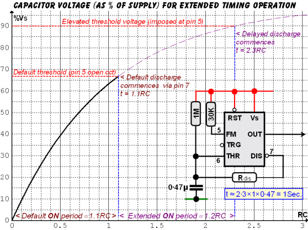
If you look at Graph 1, a target reduction from Y=66.7% (red line) to 60% (a 10% reduction) reduces the time from X=1.1 CR (blue line) to about 0.9 CR — a reduction of some 18%.
A target increase of 20% (from 66.7% to 80%) increases the time from 1.1 CR (Time Constants) to 1.6 CR — an increase of some 40%!
Other tolerances that affect the timing are the Threshold input current (negligible in the CMOS versions) and leakage into pin 7.
A way of increasing the time period up to double thus presents itself by simply strapping pin 5 with a resistor to supply, increasing the threshold voltage to which the capacitor must charge.
| Description: |
|
| Filesize: |
15.48 KB |
| Viewed: |
2009 Time(s) |
|
| Description: |
| The non-linear relationship between pin 5 Control Voltage and Time. |
|
| Filesize: |
68.49 KB |
| Viewed: |
171 Time(s) |
| This image has been reduced to fit the page. Click on it to enlarge. |
|
|
|

 Forum index » DIY Hardware and Software » Developers' Corner

