| Author |
Message |
RSFC
Joined: Sep 02, 2010
Posts: 63
Location: space lab
|
 Posted: Sun Jan 23, 2011 4:27 pm Post subject: Posted: Sun Jan 23, 2011 4:27 pm Post subject:
|
  |
|
| I builts 2 of these one is working and one is not... sorta. I did find that these actually make nice sounding passive VCAs as well as active. I can run a singal though and CV control the one that isn't working correctly (or the other one that is, unpowered) and it actually has a nice colored sound that is a bit more smooth and less aggressive than the one working actively. I'm half tempted to use it as is but I should probably figure out what the problem is. As soon as I apply power to it, no signal passes through. I'm guess it is shorted somewhere but I haven't figured it out yet. |
|
|
Back to top
|
|
 |
bassculture
Joined: Jan 23, 2011
Posts: 22
Location: france
|
| Posted: Mon Jan 24, 2011 1:48 am Post subject:
|
|
|
i suppose there shouldn't by any output without a short 
sound interresting anyway !
maybe send fotos ?
did you make any mods compared to the stock version ? |
|
|
Back to top
|
|
|
RSFC
Joined: Sep 02, 2010
Posts: 63
Location: space lab
|
| Posted: Tue Jan 25, 2011 3:55 pm Post subject:
|
|
|
| The only intentional difference is that I chose a different bias mode for each board. I think the non-working one has the "modified bias". Otherwise it should be the same. I am fairly certain that both of them can be used passively. I just get no output once I apply power to one of them.... The only other mod I did was for feedback but it works fine on one of the 2... |
|
|
Back to top
|
|
|
bassculture
Joined: Jan 23, 2011
Posts: 22
Location: france
|
| Posted: Fri Jan 28, 2011 4:12 pm Post subject:
|
|
|
anyone on the mods and ARP2600 questions ?
(previous page) |
|
|
Back to top
|
|
|
bassculture
Joined: Jan 23, 2011
Posts: 22
Location: france
|
| Posted: Mon Jan 31, 2011 6:37 am Post subject:
|
|
|
hi,
anyone on modifying the inputs and outputs to use it with an ARP2600 (20Vpp) ?
espacially impedance issues ? |
|
|
Back to top
|
|
|
PrimateSynthesis
Joined: May 02, 2008
Posts: 69
Location: U.S.A.
|
| Posted: Tue Mar 29, 2011 5:50 am Post subject:
|
|
|
| bassculture wrote: | hi,
anyone on modifying the inputs and outputs to use it with an ARP2600 (20Vpp) ?
espacially impedance issues ? |
Funny, I don't seem to be getting notices from this thread, as I just saw this now.
What, specifically are your questions regarding its use with a 2600? If you could post the impedances and voltage levels of the ARP, I'm sure someone could help. |
|
|
Back to top
|
|
|
bassculture
Joined: Jan 23, 2011
Posts: 22
Location: france
|
| Posted: Wed Mar 30, 2011 12:39 am Post subject:
|
|
|
hi mark,
i'm really glad you're around here cause i'm currently testing a CGS65 based on some of your modifications.
Thank you for sharing those !!!
about the ARP :
the signal voltage is 10Vpp
filter output is always +5Vmax, but can go beyond 10Vpp
(like +5 / -15V when you have all 5 input full)
same with the VCA
CV range is 10Vpp
envelloppe : 0 - +10V
althought the simple AR generates 0 - +8V max.
note : the preamp is really nasty and can go beyond 30Vpp (can't measure it exactly - my oscilloscope input is clipping)
so i think there's no need for modification on the voltages sides ?
for impedance, how you would mesure it ?
modifications :
i'm having trouble understanding the exact function of the LED's and diodes on the original circuit.
it doesn't sound the way it should. my two problems are :
the output of the CGS65 seems to be rectified (only positive side)
althought the output level is ok.
and i'm only having a usable range in the last 1/5 of the gain pot.
gain seem to low - can't get that "scream".
i'm going back with voltage measurements tonight or tomorow morning
P.S: really cool looking at the CGS65 waveshaping on the oscilloscope
in his own, the ARP is kind of a big waveshaping thing too... you'll never get the same thing in and out of a part of it |
|
|
Back to top
|
|
|
PrimateSynthesis
Joined: May 02, 2008
Posts: 69
Location: U.S.A.
|
| Posted: Wed Mar 30, 2011 4:13 am Post subject:
|
|
|
| bassculture wrote: |
envelloppe : 0 - +10V
althought the simple AR generates 0 - +8V max.
so i think there's no need for modification on the voltages sides ? |
It doesn't look like it. I adjusted mine so that the CV input and the Gain knob had the same range for a 0-5V envelope. Once you get it working you could adjust the resistor values for 8V or 10V.
| bassculture wrote: | | for impedance, how you would mesure it ? |
Unless the ARP has an unusually high output impedance, or unusually low input impedance, it's a non-issue.
| bassculture wrote: |
i'm having trouble understanding the exact function of the LED's and diodes on the original circuit. |
I replaced them with a resistor. I wouldn't recommend mixing my cathode circuit with the original.
| bassculture wrote: |
the output of the CGS65 seems to be rectified (only positive side)
althought the output level is ok. |
Then I would trace the signal and see where that occurs. The output should not be single-sided.
| bassculture wrote: |
and i'm only having a usable range in the last 1/5 of the gain pot.
gain seem to low - can't get that "scream". |
Then you need to figure out whether it is a problem with the CV circuit, or the audio circuit. I haven't looked at this thing in a long time, so I don't remember what the voltage range was on the control grid. Perhaps you have the offset voltage set too high, and you are burying most of the CV range? Regardless, the CV circuit is very simple. So I would trace the DC voltages to see if it is working properly. Check the voltages on pin 7 and pin 6, and pins 2 and 1, and that they are working as inverted amplifiers.
Also which op-amp did you use? |
|
|
Back to top
|
|
|
bassculture
Joined: Jan 23, 2011
Posts: 22
Location: france
|
| Posted: Wed Mar 30, 2011 7:34 am Post subject:
|
|
|
hi !
ok, i correct my mistake (i didn't removed the 2 4041 diodes)
also the initial CV trimmer was set too low.
now everything seems to work ok.
but the gain range is stil at the end of the pot curve (linear pot)
so this the modifications i take from your first post :
i just take the leds and 1,5K and diodes and replaced them with 1,2K
i will add the 47uF cap with a switch also
i modified the inputs, outputs and bias switch like will and dave do :
http://www.dragonflyalley.com/constructionCGS65tubeVCA.htm
they stick to the MOTM format which has the same voltage as the ARP
(i hope i get everything right)
in fact the gain pot is acting like a fixed CV level ?
the real "tone shaper" is the input pot.
now i'm wondering how to get a CV to control the input level
do you have any tips on how achieving this with a few components more ?
or maybe that would be better messing mith the "quality / gain" resistor
(i have 8K2 in place - but thinking about soldering a pot in there)
plugging a CV in an audio input is a great sounding option to get around this, but not the same
kind of a messy post, but any thought from an expert like you will be appreciated
thanks for sharing ! |
|
|
Back to top
|
|
|
PrimateSynthesis
Joined: May 02, 2008
Posts: 69
Location: U.S.A.
|
| Posted: Wed Mar 30, 2011 7:55 am Post subject:
|
|
|
| bassculture wrote: |
ok, i correct my mistake (i didn't removed the 2 4041 diodes)
also the initial CV trimmer was set too low.
now everything seems to work ok. |
That's good.
| bassculture wrote: |
but the gain range is stil at the end of the pot curve (linear pot)
|
Are we talking about the Gain/CV pot or the input pot? You might prefer an audio taper for the audio inputs. I used linear because that's what I had.
| bassculture wrote: |
i will add the 47uF cap with a switch also
|
You mean the cathode cap? I wouldn't use a switch because the wiring will do two things you don't want -- add an antenna, and add impedance. And I don't see a point in being able to switch it on and off. Do make sure it is on the correct side, and you use a heater resistor that can handle the current. I used a 1/2W.
| bassculture wrote: |
in fact the gain pot is acting like a fixed CV level ?
|
The Gain pot is a fixed CV level.
| bassculture wrote: |
now i'm wondering how to get a CV to control the input level
do you have any tips on how achieving this with a few components more ?
|
You mean another VCA going into the VCA?? |
|
|
Back to top
|
|
|
bassculture
Joined: Jan 23, 2011
Posts: 22
Location: france
|
| Posted: Fri Apr 01, 2011 4:40 am Post subject:
|
|
|
hi, i too, haven't been notified of your answer...
| Quote: | bassculture wrote:
but the gain range is stil at the end of the pot curve (linear pot)
Are we talking about the Gain/CV pot or the input pot? You might prefer an audio taper for the audio inputs. I used linear because that's what I had. |
i'm talking about the gain pot
if i have the intial CV trimmer higher (3/4), i have nice progressive range on that gain pot but, then the CV has an effect only if gain pot is from 0 to 1/4.
after 1/4 on gain pot, it's squashed by the fixed CV/gain
so i have my initial CV trimmer around the middle, so the CV didn't get squashed to soon when i raise the gain...
but finding the sweet spot beetween intial CV / CV in / gain is quiet... hum ... could be better
| Quote: | bassculture wrote:
now i'm wondering how to get a CV to control the input level
do you have any tips on how achieving this with a few components more ?
You mean another VCA going into the VCA?? |
maybe there's another way of doing it directly on the circuit...
plugging a CV in an audio input do not do exactly the same, but that's closer.
moving the input knob with my finger is the closest but the Human VCA has fairly poor specs )
what i'm pointing is that's the input that really has an impact on the spectrum, and that's what i want to modulate with the CV.
that would turn the circuit in a Voltage Controlled Saturator
any tips on how achieving this would gain you my eternal gratitude... and a nice meal if you ever come to my place (France)
this circuit is not just a VCA, it desserve more !
VOLTAGES :
i'm pretty surprised by them...
1 : -13,92
2 : -14,85
3 : 0.0
4 : - 14,86
5 : + 13,50
6 : - 14,39
with another tube, i got the same exept -20.06 at Pin 6...
initial CV trimmer at 12oclock, gain max, input max.
i mesured beetween the ground of my power supply and the pins.
on another thread, that was the voltage of a working unit that a user posted - i.e. not with your mods
Pin # Working Unit
1) 13.68
2) -14.96
3) -.8
4) -14.96
5) 11.81
6) -15.02
...
note i didn't solder the 47uF beetween pin 2 & ground, but i don't think that interact...
I didn't follow your mods 100% because some things where unclear...
i will do a post with my questions asap.
thanks again ! |
|
|
Back to top
|
|
|
PrimateSynthesis
Joined: May 02, 2008
Posts: 69
Location: U.S.A.
|
| Posted: Fri Apr 01, 2011 8:56 am Post subject:
|
|
|
| bassculture wrote: |
so i have my initial CV trimmer around the middle, so the CV didn't get squashed to soon when i raise the gain... |
I would set the trimmer such that there is no output when the Gain pot and CV input is zero. You can change the CV scaling by changing its input resistor. See above.
Also, the grid bias has a significant effect on how it sounds and functions.
You could also change where the suppression grid is connected, making its voltage more positive increases the gain of the tube. |
|
|
Back to top
|
|
|
bassculture
Joined: Jan 23, 2011
Posts: 22
Location: france
|
| Posted: Sun Apr 03, 2011 3:51 pm Post subject:
|
|
|
| Quote: | | I would set the trimmer such that there is no output when the Gain pot and CV input is zero. You can change the CV scaling by changing its input resistor. See above. |
thanks
| Quote: | | You could also change where the suppression grid is connected, making its voltage more positive increases the gain of the tube. |
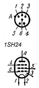
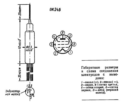
thank you again, can you confirm this tube pinout :
1 - heater
2 - heater
3 - suppression grid
4 - screen grid
5 - control grid
6 - cathode
7 - anode
can't go further by myself without being sure of it
| Quote: | | Also, the grid bias has a significant effect on how it sounds and functions. |
did the 220n DC blocking caps (i assume) play a part in the the biasing too ?
i haven't been able to find reliable biasing infos on this tube.
do you have any ?
thanks again ! |
|
|
Back to top
|
|
|
PrimateSynthesis
Joined: May 02, 2008
Posts: 69
Location: U.S.A.
|
| Posted: Tue Apr 05, 2011 8:50 am Post subject:
|
|
|
| bassculture wrote: |
thank you again, can you confirm this tube pinout :
1 - heater
2 - heater
3 - suppression grid
4 - screen grid
5 - control grid
6 - cathode
7 - anode
|
That is not correct. This tube uses a filamentary cathode, so pins 1 and 2 are the heater and the cathode. Pin 3 is a shield. Pin 4 is the suppression grid. Pin 6 is the signal grid.
http://dl3jin.de/mig40-data/1sh24b.pdf
| Description: |
|
| Filesize: |
9.61 KB |
| Viewed: |
29393 Time(s) |
|
| Description: |
|
| Filesize: |
22.05 KB |
| Viewed: |
29393 Time(s) |
|
|
|
|
Back to top
|
|
|
bassculture
Joined: Jan 23, 2011
Posts: 22
Location: france
|
|
|
Back to top
|
|
|
PrimateSynthesis
Joined: May 02, 2008
Posts: 69
Location: U.S.A.
|
| Posted: Fri Apr 08, 2011 6:48 am Post subject:
|
|
|
| bassculture wrote: |
1// i've messed with quality / gain resistor : i put a reostat between that resistor and +15V. even with a 50K pot (58,2K total R), nothing "strange" happens (has ken stated - your cathode circuit maybe responsible for that), just more gain  |
I didn't put any effort into trying to get more gain out of the tube, but in getting a clean signal over a wide frequency range. Most VCA's are voltage controlled attenuators in practice. However, more gain might be an improvement, but who knows how much current it can handle? Sometimes I think some input gain could be helpful, and I might try decreasing the input resistors to the summing amp...
| bassculture wrote: |
2// i'm gonna try that :
| Quote: | | Wire the grid to a rheostat, then to the wiper of a pot set up as a voltage divider between -15V and ground |
do i need a minimum resistance between the grid and the reostat (like the 330K i have now) ?
i mean as long as the grid is negative relative to the anode, it works ?
for exemple if the grid (pin 6) is directly connected to the ground or to -Ve?
| Quote: | | If you used a buffer, you could even normal the -15V to a CV input jack. |
|
That's if you wanted CV controlled bias, but I haven't given it much thought, so please ignore whatever I might have said there 
The biasing on this thing is just weird, as most tubes do not use a bipolar supply, and the cathode is generally near ground in similar circuits. Regardless, there needs to be a minimum AC impedance between the signal and ground or either rail. Frankly, I'm surprised such a small resistor between the grid and negative rail works as well as it does.
Also that schematic you posted looks rather confused. I don't know where you got an "R4" of 100K, where you think it connects. The audio signal is AC coupled to the grid. Why don't you try building either my circuit, or Ken's circuit, without changing anything, and see if that works? |
|
|
Back to top
|
|
|
bassculture
Joined: Jan 23, 2011
Posts: 22
Location: france
|
| Posted: Fri Apr 08, 2011 7:36 am Post subject:
|
|
|
hi
don't want to bother you !
i go to sleep smarter everyday this week
thank you !
for the moment i got a working circuit and i'm pretty satisfied with what i can do with it.
i think i get best of both (ken and yours) approach for my needs.
but as long as i'm building a few a these for myself and for some friends...
before going into the building process (schaeffer faceplates / heatshrink and all that...) i wanted to do my best to see what extra features are possible to add.
i'm looking for either that "clean" tube warm/comp sound and also for a crazy/funky waveshaper.
schematic :
this is my first attempt to "design" a "circuit" ))
R4 is a mistake... i'm not an expert... just learning by myself ! |
|
|
Back to top
|
|
|
bassculture
Joined: Jan 23, 2011
Posts: 22
Location: france
|
| Posted: Fri Apr 08, 2011 8:27 am Post subject:
|
|
|
and...
i was thinking of using the other half of the TL072 as another inverting buffer for negative feedback |
|
|
Back to top
|
|
|
bassculture
Joined: Jan 23, 2011
Posts: 22
Location: france
|
| Posted: Thu Jul 21, 2011 3:40 pm Post subject:
|
|
|
hi everybody,
just to let you know i finally get to it
thank you marc fot the help !
so i wired a pot beetween -15 and ground to bias pin 6, and the same with pin 4.
the two settings interact, and allowed to change the set of harmonics the tube provide.
feeding the circuit with a sine wave, it's really obvious looking at a spectrum analyser 
i used 100k lin pot, but i have to work here because the load it adds (i suppose) modified the biasing point where the clean signal is. |
|
|
Back to top
|
|
|
sonicwarrior

Joined: Dec 22, 2005
Posts: 266
Location: Cologne, Germany
|
|
|
Back to top
|
|
|
sonicwarrior
Joined: Dec 22, 2005
Posts: 266
Location: Cologne, Germany
|
| Posted: Mon Jun 18, 2012 10:03 am Post subject:
|
|
|
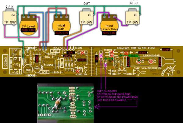
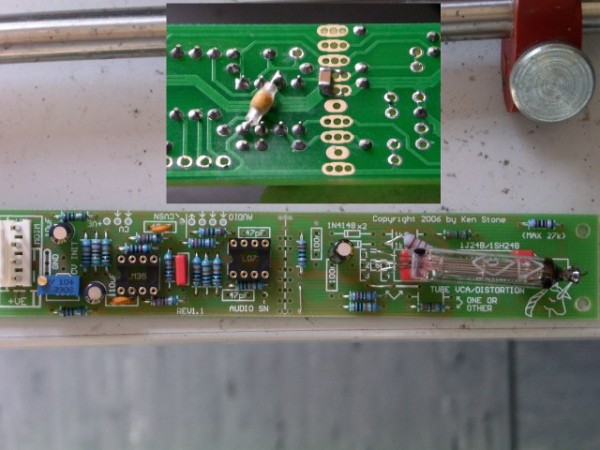
I installed most Mods today (no bias switch, left that like the original schematic):
| PrimateSynthesis wrote: | | Here are some pictures showing the grid bias wiring and cathode bypass modifications. |
I'm a bit confused as you said you omitted the 47 pF caps although they are still on the pics.
Unfortunately I forgot to add heat shrink tube before installing the tube but the distances between the wire looks still OK.
I've attached a pic of my PCB including a pic of the back with the 100Ns caps for the OP275. I used one 1206 SMD cap as there is a gap between ground and V- where it fits exactly and used an axial ceramic cap between ground and V+.
Used a 51K instead of a 50K/49K9 for the CV input because I had that at hand and guessed 1K doesn't make much difference (my DMM measured 50K9).
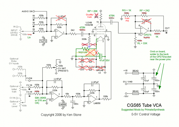
Plus I've compiled the Mods I installed into the original schematic because it's easier to compare this way. Attached that, too. I hope I didn't miss anything besides the bias switch which I omitted on purpose as I want to use it for dirty stuff anyway and don't need a clean position (I guess).
| Description: |
| PCB stuffed with PrimateSynthesis Mods |
|
| Filesize: |
80.33 KB |
| Viewed: |
411 Time(s) |
| This image has been reduced to fit the page. Click on it to enlarge. |
|
| Description: |
| Compiled PrimateSynthesis Mods without the bias switch (Edit: Corrected the position of the 47uF) |
|
| Filesize: |
59.6 KB |
| Viewed: |
601 Time(s) |
| This image has been reduced to fit the page. Click on it to enlarge. |
|
|
|
|
Back to top
|
|
|
sonicwarrior
Joined: Dec 22, 2005
Posts: 266
Location: Cologne, Germany
|
|
|
Back to top
|
|
|
Aum Generator
Joined: Aug 15, 2011
Posts: 11
Location: Bratislava
|
|
|
Back to top
|
|
|
sonicwarrior
Joined: Dec 22, 2005
Posts: 266
Location: Cologne, Germany
|
| Posted: Sun Aug 26, 2012 2:02 pm Post subject:
|
|
|
On the last one (the other one is screwed in place and I was too lazy to look at that one too) I used 50K pots. But as these are just voltage dividers or attenuators it won't make a difference here.
Your drawing looks good at first sight but you are missing the bias jumper. The PCB image doesn't show the current Rev 1.1 PCB because the different bias possibilities are not on it. |
|
|
Back to top
|
|
|
Aum Generator
Joined: Aug 15, 2011
Posts: 11
Location: Bratislava
|
| Posted: Sun Aug 26, 2012 2:12 pm Post subject:
|
|
|
| sonicwarrior wrote: | | On the last one (the other one is screwed in place and I was too lazy to look at that one too) I used 50K pots. But as these are just voltage dividers or attenuators it won't make a difference here. |
thanks
| sonicwarrior wrote: |
Your drawing looks good at first sight but you are missing the bias jumper. The PCB image doesn't show the current Rev 1.1 PCB because the different bias possibilities are not on it. |
i was also missing the 50k instead of 100k on CV in. corrected.
the pcb picture on ken's site is different than pcb. when placing the 47uF i had to draw pads nearby the tube's pads, because they were not on the picture.
going to check info about the bias jumper in PDF. Only thing i see on the schematic and not on my picture is that BLUE/PURPLE arrow. Is it that?
Last edited by Aum Generator on Sun Aug 26, 2012 2:40 pm; edited 1 time in total |
|
|
Back to top
|
|
|
|

 Forum index » DIY Hardware and Software » Ken Stone designs - CGS