| Author |
Message |
LetterBeacon
Joined: Mar 18, 2008
Posts: 454
Location: London, UK
|
 Posted: Sun Mar 10, 2013 4:26 pm Post subject:
Power Supply problem Posted: Sun Mar 10, 2013 4:26 pm Post subject:
Power Supply problem |
  |
|
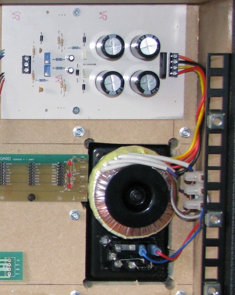
I've recently taken my DIY modular out of storage and installed two MFOS adjustable power supplies in it to replace the old 'Power One' style one I had in there.
I built both supplies, switched the modular on, and dialled in +/-15VDC on both PCBs no problem.
I have PSU 1 feeding Bus Board 1 with molex connectors and PSU 2 feeding Bus Board 2 with euro connectors. The bus boards' grounds are connected together.
When I plugged all the modules in -some on Bus Board 1 and some on Bus Board 2- I noticed the positive rail on Bus Board 1 dropped slowly until it hit about +5VDC.
At first I suspected thermal shut down, but all the regulators are heatsinked, and when I felt them, they were running cool. I didn't have this problem when nothing was plugged into them. I also noticed that I'm only measuring about 7VAC on the secondaries of the transformers.
I'm wondering if this is a current problem.
Each PSU PCB can provide a maximum of 1.5A.
Each PSU PCB is fed by a 80VA 115/ 230 > 2x15V transformer. The colour codes of the wires are as follows:
Primary
Blue - 0v
Grey - 115v
Violet - 0v
Brown - 115v
Secondary
Orange - 0v
Yellow - 15v
Black - 0v
Red - 15v
Maybe I have the wiring of the transformers mixed up. This is how I currently have them:
Primary
Grey + Violet tied together
Blue goes to my fuse
Brown goes to the neutral of my IEC socket
As I understand it, this wires my transformer up for 230VAC operation.
Secondary
Yellow + Black tied together and go to the CT pad on the PSU PCB
Orange goes to AC input pad on PSU PCB
Red goes to AC input pad on PSU PCB
Have I got this wired up correctly? Is this the reason I'm only getting 7VAC at the input of the PSU PCB? And because of this the regulator is struggling to make it up to +15VDC and shuts down?
Any help would be much appreciated! |
|
|
Back to top
|
|
 |
Broadwave

Joined: Feb 16, 2007
Posts: 347
Location: Manchester UK
Audio files: 6
|
| Posted: Mon Mar 11, 2013 12:18 am Post subject:
|
|
|
@Letterbeacon
I have exactly the same setup, but it's working fine. I've only just woken up, but I'll take a look inside my synth and check everything once I've shaken myself.
But from what you've described, all the wiring seems ok.
EDIT - I've had a cup of tea and my mind's clear now 
I have the primary blue going to neutral and the brown to the fuse (but I don't think that will make much difference)
But... you've used a 15-0-15 transformer, and that may be the problem. I've got 18-0-18 which allows for the 3 volt drop that the regulators require to function properly.
Can anyone else chip in here?
| Description: |
|
| Filesize: |
486.04 KB |
| Viewed: |
117 Time(s) |
| This image has been reduced to fit the page. Click on it to enlarge. |
|
_________________
Kronos 2-88, Kronos 61, Studiologic Sledge V2/SL, Broadwave ARP 2600EX, Broadwave 18U ARP based Eurorack Modular, Broadwave Minimoog Clone, GEM S2 Turbo.
Synth DIY Projects
Musical Doodlings |
|
|
Back to top
|
|
|
LetterBeacon
Joined: Mar 18, 2008
Posts: 454
Location: London, UK
|
| Posted: Mon Mar 11, 2013 1:20 am Post subject:
|
|
|
Hi Andy -thanks for the reply!
The reason I used 15v transformers is because they're rated for 2.67A. Doesn't that mean that if I'm pulling 2.67A the transformer output will be 15v? As I'll only be pulling 1.5A maximum, the transformer output will be higher.
Or have I got that totally wrong?
Are yours 80VA? How much AC do you measure at the input of the PSU boards? |
|
|
Back to top
|
|
|
Broadwave
Joined: Feb 16, 2007
Posts: 347
Location: Manchester UK
Audio files: 6
|
| Posted: Mon Mar 11, 2013 3:25 am Post subject:
|
|
|
Unfortunately, even if your transformer is capable of supplying 1.5A per rail, in reality you'll never be able to get that... The more current you draw from your regulator, the hotter it will get, eventually leading to thermal shut down.
As a guideline I only ever work to half the current required i.e for a 1.5A rail, I assume that I'm going to be able to safely draw around 700ma MAX before things get unreliable (voltage drops/overheating).
The regulators drop 2/3v for them to work efficiently. In other words, your 15-0-15 transformer effectively only provides 12/13v per rail (I'm simplifying the wording here, but I'm sure you get my drift). So trying to keep a steady +/-15v isn't going to work... which is why you really need an 18-0-18 transformer.
As an experiment, you could try adjusting your PSU output to +/-12v, then plug in a few modules to see if the voltage is stable - I suspect it will be.
Still no body else to chip in?
_________________
Kronos 2-88, Kronos 61, Studiologic Sledge V2/SL, Broadwave ARP 2600EX, Broadwave 18U ARP based Eurorack Modular, Broadwave Minimoog Clone, GEM S2 Turbo.
Synth DIY Projects
Musical Doodlings |
|
|
Back to top
|
|
|
PHOBoS

Joined: Jan 14, 2010
Posts: 5609
Location: Moon Base
Audio files: 705
|
| Posted: Mon Mar 11, 2013 5:20 am Post subject:
|
|
|
| AndyR1960 wrote: | | Still no body else to chip in? |
I don't really have anything to add, but when I build my own +/-15V supply I also started with a 2x 15V transformer
(allready had it). But even without a load the voltage was allready to low (keep in mind that there can be
fluctations in the mains voltage). So I changed it to a 2x 18V AC transformer and that worked fine. I used the
2x15V AC to make a 2x12V PSU. So yeah, since it's working fine without a load,. I guess the voltage just drops
too low for the regulators with a load. Did you try adding one module at a time ? Maybe it's one module causing it.
_________________
"My perf, it's full of holes!"
http://phobos.000space.com/
SoundCloud BandCamp MixCloud Stickney Synthyards Captain Collider Twitch YouTube |
|
|
Back to top
|
|
|
LetterBeacon
Joined: Mar 18, 2008
Posts: 454
Location: London, UK
|
| Posted: Mon Mar 11, 2013 5:32 am Post subject:
|
|
|
Thanks for the replies!
Yes, it starts to lower as I start adding modules. It's only one PSU PCB that does that though, strangely.
Looks like I'll be placing an order for two more transformers then! |
|
|
Back to top
|
|
|
The Bad Producer

Joined: Mar 08, 2009
Posts: 282
Location: The Manhole
|
|
|
Back to top
|
|
|
Skrog Productions

Joined: Jan 07, 2009
Posts: 1196
Location: Scottish Borders
Audio files: 155
|
| Posted: Mon Mar 11, 2013 12:06 pm Post subject:
|
|
|
Hullo folks
In my experience the toroidal transformers pump out a little more than the marked output voltage , i used to run a 120Va toroidal 18 / 0 - 18 / 0 for my big blue coloured system, loading is 2amps per rail.
I was getting about 20V at the secondaries , my system is 95 % 12V modules and the resultant 8V drop over the 12V regs dissipated as heat , searing heat , i could have had a rotisserie module over the regs (mmmm roast chicken) hehehe , I now use a 15-0 / 15-0 Toroidal for my mostly 12V system and, have made 6 distro boards with regulators per distro with large cross sectional area cableing from bridges to each distro board everything runs sensibly now .
Your modular problem .... hmmm , try un-tying the 0V link that you say you've coupled between the two seperate distro boards , see if they behave ok ..... were they linked right at the capacitor 0V points on each power supply board ? or at the end of a chain of sockets for modules (distro boards)
Dave. |
|
|
Back to top
|
|
|
LetterBeacon
Joined: Mar 18, 2008
Posts: 454
Location: London, UK
|
| Posted: Mon Mar 11, 2013 12:08 pm Post subject:
|
|
|
Hi Dave,
That's interesting to know.
The grounds are tied together at the distro boards, a little way away from the filter caps. I'll try untying them and see what happens. |
|
|
Back to top
|
|
|
Skrog Productions
Joined: Jan 07, 2009
Posts: 1196
Location: Scottish Borders
Audio files: 155
|
| Posted: Mon Mar 11, 2013 12:20 pm Post subject:
|
|
|
i aslo had to tie my 0V connection at my capps to mains earth , i found a slight potential measured on my power supply between 0V & earth.
For me , this reduced a bad hum i was getting before.
Dave. |
|
|
Back to top
|
|
|
Skrog Productions
Joined: Jan 07, 2009
Posts: 1196
Location: Scottish Borders
Audio files: 155
|
| Posted: Mon Mar 11, 2013 12:34 pm Post subject:
|
|
|
i'd love to see a nice pvc shroud over the entire IEC socket rear & a wee cover over the 15A connector strip , safety first 
Dave. |
|
|
Back to top
|
|
|
diablojoy

Joined: Sep 07, 2008
Posts: 809
Location: melbourne australia
Audio files: 11
|
| Posted: Mon Mar 11, 2013 6:46 pm Post subject:
|
|
|
A long shot but Its possible you have the phase incorrect on your windings
if you have an old analogue meter its easy to check
you will see a very slight positive or negative kick of the meter on connecting the meter probes this gives you an indication of the winding direction
should be in series
_________________
In an infinite universe one might very well
ask where the hell am I
oh yeah thats right the land of OZ
as good an answer as any |
|
|
Back to top
|
|
|
Osal
Joined: Aug 16, 2011
Posts: 147
Location: Here
|
| Posted: Tue Mar 12, 2013 12:19 am Post subject:
|
|
|
| The Bad Producer wrote: | | Full props to Osal for that! |
Thanks! In that thread there are formulas for the voltage ratings of different parts of the power supply. Like the transformer, that is discussed here, for example, or for calculate the immunity to mains voltage drop. You can just copy/paste those formulas on Google and replace the terms by values and see the result. If there is something non understandable due my English level send me a message. If I can explain something better, let me know please.
| LetterBeacon wrote: | | The reason I used 15v transformers is because they're rated for 2.67A. Doesn't that mean that if I'm pulling 2.67A the transformer output will be 15v? As I'll only be pulling 1.5A maximum, the transformer output will be higher. |
Yes, that is right. But notice that in these power supplies when 1A DC is flowing in the regulator output, 1.6A AC is flowing in the secondaries. There is a part of that secondaries' current that flows through the filter capacitors.
For this example, when 2.67A AC are flowing in the secondaries, the voltage across one secondary is 15VAC when the mains electricity is the nominal value of the primary.
And 1.67A DC is flowing in the regulator's output.
If the voltage regulation of a 80VA toroidal transformer is 11%, the voltage across a secondary will be a 11% higher under no load. For a 15VAC secondary it would be approximately 16.6VAC. This is 1.6VAC higher. So, for example, if this transformer would deliver half of its rated current, we could expect roughly a voltage across the a secondary 0.8VAC higher than its nominal value. This would be 15.8VAC (1.3A AC in the secondaries and 0.8A DC in the regulators' output).
You could also measure and estimate it as I describe in the thread mentioned by Bad Producer.
| AndyR1960 wrote: | Unfortunately, even if your transformer is capable of supplying 1.5A per rail, in reality you'll never be able to get that... The more current you draw from your regulator, the hotter it will get, eventually leading to thermal shut down.
As a guideline I only ever work to half the current required i.e for a 1.5A rail, I assume that I'm going to be able to safely draw around 700ma MAX before things get unreliable (voltage drops/overheating). |
Yes I do agree.
Doesn't matter the current rating of the regulator, the bottleneck of a power supply design is the power dissipation if it is passive.
_________________
electronic-sea.net |
|
|
Back to top
|
|
|
Osal
Joined: Aug 16, 2011
Posts: 147
Location: Here
|
| Posted: Tue Mar 12, 2013 12:33 am Post subject:
|
|
|
| LetterBeacon wrote: | Thanks for the replies!
Yes, it starts to lower as I start adding modules. It's only one PSU PCB that does that though, strangely.
Looks like I'll be placing an order for two more transformers then! |
Yes, I do agree that the transformer for a +/-15V supply should be a a 36VCT as Andy already have said.
This is in order to have a convenient immunity to mains voltage drop and acceptable regulation. If you have an oscilloscope you can see what happens to the DC output when there is not enough difference within Vin and Vout. Place one probe at the regulator's input and the other in the regulator's output and set both channels at the same horizontal level. Observe both channels meanwhile you adjust the voltage output up to 20V (be sure that the output capacitors are conveniently rated!) you will see how the ripple appears in the regulator's output. (EDIT: NO modules connected!!!)
However, I think that the problem that you describe has another cause.
Could you first replace the regulator of the faulty rail?
_________________
electronic-sea.net
Last edited by Osal on Tue Mar 12, 2013 2:24 am; edited 1 time in total |
|
|
Back to top
|
|
|
Osal
Joined: Aug 16, 2011
Posts: 147
Location: Here
|
| Posted: Tue Mar 12, 2013 12:47 am Post subject:
|
|
|
| Skrog Productions wrote: |
In my experience the toroidal transformers pump out a little more than the marked output voltage |
Hi Dave. All the transformers I tested were, under the rated load, approximately the same voltage than the voltage rated by the manufacturer.
The two causes because you can read higher AC voltage across the secondary are:
1-The voltage regulation. It happens when the actual current output is lower than the rated current.
2-The mains voltage is higher than the rated voltage in the primary's transformer. This is easy to happen in the UK, where the mains voltage is still 240VAC and the rated voltage in the primary's transformers use to be 230VAC
_________________
electronic-sea.net |
|
|
Back to top
|
|
|
Osal
Joined: Aug 16, 2011
Posts: 147
Location: Here
|
| Posted: Tue Mar 12, 2013 12:55 am Post subject:
|
|
|
| diablojoy wrote: | A long shot but Its possible you have the phase incorrect on your windings
if you have an old analogue meter its easy to check
you will see a very slight positive or negative kick of the meter on connecting the meter probes this gives you an indication of the winding direction
should be in series |
Another way to check it is measuring the frequency off the ripple at the regulator's input. If the secondaries are in phase you will read 50hz. If they are out of phase, as they must be, you will read 100hz.
_________________
electronic-sea.net |
|
|
Back to top
|
|
|
Broadwave
Joined: Feb 16, 2007
Posts: 347
Location: Manchester UK
Audio files: 6
|
| Posted: Tue Mar 12, 2013 3:41 am Post subject:
|
|
|
| Skrog Productions wrote: | i'd love to see a nice pvc shroud over the entire IEC socket rear & a wee cover over the 15A connector strip , safety first
Dave. |
Ooops... I agree totally, but you know what it's like when you've built a new toy - Little things like that tend to be put aside "'til later" 
_________________
Kronos 2-88, Kronos 61, Studiologic Sledge V2/SL, Broadwave ARP 2600EX, Broadwave 18U ARP based Eurorack Modular, Broadwave Minimoog Clone, GEM S2 Turbo.
Synth DIY Projects
Musical Doodlings |
|
|
Back to top
|
|
|
LetterBeacon
Joined: Mar 18, 2008
Posts: 454
Location: London, UK
|
| Posted: Wed Mar 13, 2013 5:04 am Post subject:
|
|
|
| Thanks very much for the info Osal. My 80VA 36VCT transformers arrived today so I'll have a go at hooking them up this evening. |
|
|
Back to top
|
|
|
capicoso
Joined: Nov 19, 2012
Posts: 128
Location: Argentina
|
| Posted: Wed Mar 13, 2013 8:53 pm Post subject:
|
|
|
| LetterBeacon wrote: | | Thanks very much for the info Osal. My 80VA 36VCT transformers arrived today so I'll have a go at hooking them up this evening. |
Hey, just curious. What is the "80VA"? What does VA mean? My main language is spanish so we name some electronic things different... i wonder because i'm buying a 36VCT too(this is 18+18 right?) But i just told the guy who makes them that i needed a 36VCT 1.5A transformer... thanks
edit: nevermind, i checked and i suppose it's wattage. I just don't know how much i'd need |
|
|
Back to top
|
|
|
Osal
Joined: Aug 16, 2011
Posts: 147
Location: Here
|
| Posted: Thu Mar 14, 2013 12:40 am Post subject:
|
|
|
| capicoso wrote: | | LetterBeacon wrote: | | Thanks very much for the info Osal. My 80VA 36VCT transformers arrived today so I'll have a go at hooking them up this evening. |
Hey, just curious. What is the "80VA"? What does VA mean? My main language is spanish so we name some electronic things different... i wonder because i'm buying a 36VCT too(this is 18+18 right?) But i just told the guy who makes them that i needed a 36VCT 1.5A transformer... thanks
edit: nevermind, i checked and i suppose it's wattage. I just don't know how much i'd need |
Hola Capicoso,
VA is volt-ampere http://en.wikipedia.org/wiki/Volt-ampere
The transformers use to be specified with this unity.
For example a 36VCT and 1.5A (36V*1.5A=54VA) is a 54 VA transformer. Remember that with this transformer the maximum current you should output from the power supply is 0.8A.
Si te están haciendo el transformador por encargo, asegúrate de que el voltaje en los secundarios sea 36VAC cuando el transformador este dando 1.5A AC. (Sin conectar, el voltaje será mas alto.)
_________________
electronic-sea.net |
|
|
Back to top
|
|
|
Osal
Joined: Aug 16, 2011
Posts: 147
Location: Here
|
| Posted: Thu Mar 21, 2013 7:23 am Post subject:
|
|
|
| LetterBeacon wrote: | | Thanks very much for the info Osal. My 80VA 36VCT transformers arrived today so I'll have a go at hooking them up this evening. |
Hey Letter, you're very welcome. I'm very curious to know what was the cause of the symptoms failure you described. Please let us know if it is working now.
_________________
electronic-sea.net |
|
|
Back to top
|
|
|
LetterBeacon
Joined: Mar 18, 2008
Posts: 454
Location: London, UK
|
| Posted: Thu Mar 28, 2013 7:56 am Post subject:
|
|
|
Sorry, I've only just seen your reply.
I bought a pair of 0-18v 0-18v transformers and put them in, but when I was installing them, I noticed the ground from one of the PSU PCBs had come loose from the screw terminal, which is I think was causing the problem.
Now I've got the new transformers in, everything works great!
Thanks again for your help. |
|
|
Back to top
|
|
|
Osal
Joined: Aug 16, 2011
Posts: 147
Location: Here
|
| Posted: Sun Mar 31, 2013 4:40 pm Post subject:
|
|
|
| LetterBeacon wrote: | Sorry, I've only just seen your reply.
I bought a pair of 0-18v 0-18v transformers and put them in, but when I was installing them, I noticed the ground from one of the PSU PCBs had come loose from the screw terminal, which is I think was causing the problem.
Now I've got the new transformers in, everything works great!
Thanks again for your help. |
Thanks, glad to hear that.
_________________
electronic-sea.net |
|
|
Back to top
|
|
|
|

 Forum index » DIY Hardware and Software
