| Author |
Message |
SineHacker

Joined: Mar 09, 2010
Posts: 99
Location: United Kingdom
|
 Posted: Tue Mar 05, 2013 7:02 am Post subject:
Possible ground issue? Posted: Tue Mar 05, 2013 7:02 am Post subject:
Possible ground issue? |
  |
|
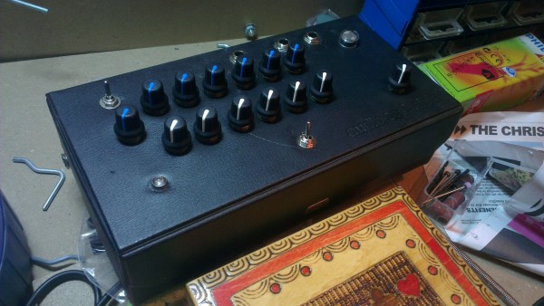
I am working on a basic drone instrument that is based around a CMOS 40106, I want to run it through a LM386 because I do some things to the gates/oscillators that makes them sound good but makes them quite quiet, and each oscillator has a separate volume pot
The problem is, if I power both chips from one battery everything sounds like battered shit, which I'm fairly sure is to do with the 40106 making the ground really noisey - If I use two batteries then it sounds fine
Another problem is that I am thinking of adding one of my crappy PT2399 based delay circuits to it as well which needs to run at 5v and 5v regulators eat 9v batteries for breakfast so I was hoping I could use a single power supply for everything from the wall.
Soooo, if I use a separate regulator for each part of the circuit would that by any chance give some separation of grounds? Actually even writing that down makes me think that will do nothing as I think the ground is linked up and unaffected by the regulator - any suggestions?
The current signal path is like this: 40106 oscillator to voltage divider (volume) x 6, so there are 6 oscillators that I sum to a 2n3819 and that goes into the lm386 - this currently goes straight to the output but I want to add the delay circuit here to try and add a crude chorus like quality to the sound. I would like to use a 7809 for the LM386 a 7805 for the PT2399 and a LM317 variable for the 40106 all powered from a 12v DC supply - I have never used multiple regulators so any tips on this would be good, I'm just going to run with it for now and experiment
Rather than trying to describe where the circuit is grounded at each point, I will draw a schematic tomorrow (at work till 9pm tonight!) and post it to help with the explanation if needed, but any thoughts on separating the ground or perhaps taming CMOS ground noise would be great!!
_________________
aidanrtaylor.co.uk |
|
|
Back to top
|
|
 |
elmegil

Joined: Mar 20, 2012
Posts: 2177
Location: Chicago
Audio files: 16
|
| Posted: Tue Mar 05, 2013 8:25 am Post subject:
|
|
|
| Have you put bypass caps on all your chips power supply pins? |
|
|
Back to top
|
|
|
SineHacker
Joined: Mar 09, 2010
Posts: 99
Location: United Kingdom
|
| Posted: Tue Mar 05, 2013 8:38 am Post subject:
|
|
|
| elmegil wrote: | | Have you put bypass caps on all your chips power supply pins? |
Yeah I always do - and definitely with the LM386!! the noisey beast it is... I'm using 1 micro-farad caps for it so maybe I will try something fatter next
_________________
aidanrtaylor.co.uk |
|
|
Back to top
|
|
|
bubzy

Joined: Oct 27, 2010
Posts: 594
Location: United Kingdom
Audio files: 64
|
| Posted: Tue Mar 05, 2013 8:51 am Post subject:
|
|
|
how does it sound at the output of your summing transistor?
_________________
_Richard_  |
|
|
Back to top
|
|
|
elmegil
Joined: Mar 20, 2012
Posts: 2177
Location: Chicago
Audio files: 16
|
| Posted: Tue Mar 05, 2013 8:51 am Post subject:
|
|
|
Just checking
I've never seen 1uF or bigger caps used as bypasses though. Usually I see 1uF or 10uF on the main supply line in, and then .1uF or .01uF caps for bypasses.
Sorry I don't have anything more helpful to suggest.... |
|
|
Back to top
|
|
|
SineHacker
Joined: Mar 09, 2010
Posts: 99
Location: United Kingdom
|
| Posted: Tue Mar 05, 2013 9:00 am Post subject:
|
|
|
@ Elmegil: ok I will try it that way cheers (should have brought it with me to work!)
| bubzy wrote: | | how does it sound at the output of your summing transistor? |
Not sure actually, I added it quite late in the game after I had been playing with the LM386 for a while - I can't quite remember why I added the 2n3819 but I do remember that I liked the result I got - but I have only listened to it post-LM386 so far - I will investigate
_________________
aidanrtaylor.co.uk |
|
|
Back to top
|
|
|
SineHacker
Joined: Mar 09, 2010
Posts: 99
Location: United Kingdom
|
| Posted: Tue Mar 05, 2013 9:17 am Post subject:
|
|
|
Have you guys got any experience with rail splitters/virtual ground/virtual dual-supply
I'm not sure if this only really applies to op-amps that require a dual-supply, but there is some interesting info here: http://tangentsoft.net/elec/vgrounds.html
_________________
aidanrtaylor.co.uk |
|
|
Back to top
|
|
|
SineHacker
Joined: Mar 09, 2010
Posts: 99
Location: United Kingdom
|
| Posted: Tue Mar 05, 2013 2:57 pm Post subject:
|
|
|
Hey again, yeah it was to do with choice of bypassing capacitors - I used 10uf across the supply and 0.1uf at the +v pin of each chip as elmegil suggested and that properly stabilised the circuit. So thanks!
I also checked the signal at the transistor and it is clear there but the lm386 gives it a nice boost anyway, I might try without the transistor next
thanks again
_________________
aidanrtaylor.co.uk |
|
|
Back to top
|
|
|
bubzy
Joined: Oct 27, 2010
Posts: 594
Location: United Kingdom
Audio files: 64
|
| Posted: Tue Mar 05, 2013 3:41 pm Post subject:
|
|
|
| SineHacker wrote: | Have you guys got any experience with rail splitters/virtual ground/virtual dual-supply
I'm not sure if this only really applies to op-amps that require a dual-supply, but there is some interesting info here: http://tangentsoft.net/elec/vgrounds.html |
virtual grounds are evil 
if you must use one, use the buffered type
_________________
_Richard_ |
|
|
Back to top
|
|
|
SineHacker
Joined: Mar 09, 2010
Posts: 99
Location: United Kingdom
|
| Posted: Wed Mar 06, 2013 12:59 am Post subject:
|
|
|
| bubzy wrote: |
virtual grounds are evil
if you must use one, use the buffered type |
yeah... I was getting a bit ahead of myself 
_________________
aidanrtaylor.co.uk |
|
|
Back to top
|
|
|
SineHacker
Joined: Mar 09, 2010
Posts: 99
Location: United Kingdom
|
|
|
Back to top
|
|
|
bubzy
Joined: Oct 27, 2010
Posts: 594
Location: United Kingdom
Audio files: 64
|
| Posted: Tue Mar 12, 2013 1:17 am Post subject:
|
|
|
what's it sound like?!
_________________
_Richard_ |
|
|
Back to top
|
|
|
SineHacker
Joined: Mar 09, 2010
Posts: 99
Location: United Kingdom
|
|
|
Back to top
|
|
|
bubzy
Joined: Oct 27, 2010
Posts: 594
Location: United Kingdom
Audio files: 64
|
| Posted: Tue Mar 12, 2013 9:28 am Post subject:
|
|
|
sounds good man!
needs more wubs
_________________
_Richard_ |
|
|
Back to top
|
|
|
PHOBoS

Joined: Jan 14, 2010
Posts: 5603
Location: Moon Base
Audio files: 705
|
|
|
Back to top
|
|
|
SineHacker
Joined: Mar 09, 2010
Posts: 99
Location: United Kingdom
|
| Posted: Tue Mar 12, 2013 10:07 am Post subject:
|
|
|
Yeah, I think I need to adjust the wub control... but really - I want the delay effect to be less subtle I think, you don't really hear it until the feedback is on the brink of self-oscilation, needs a mix control or some adjustment. I pretty much built the delay line from the PT2399 datasheet but switched out some of the capacitors to improve the sound quality (by trial and error!!). I am wondering if I can improve the volume by changing the resistor values between the lpf input and output - or what I presume is the main input but the pins are marked as LPF in and out. It's a great chip by any means!
_________________
aidanrtaylor.co.uk |
|
|
Back to top
|
|
|
PHOBoS
Joined: Jan 14, 2010
Posts: 5603
Location: Moon Base
Audio files: 705
|
|
|
Back to top
|
|
|
SineHacker
Joined: Mar 09, 2010
Posts: 99
Location: United Kingdom
|
| Posted: Tue Mar 26, 2013 5:55 am Post subject:
|
|
|
Neat, that's very helpful - I have a new project on the go now where I am going to revisit the pt2399 so I think I will start again from scratch
I am going to use a basic 4017 based 4 step sequencer to blink LED's and these will be used to opto-couple a single audio signal across 4 delays, the idea is to chop a signal in a sequence to each delay input. If it sounds as good as my brain is making out then it will be FUN
gonna put it in a vintage cornflakes tin
_________________
aidanrtaylor.co.uk |
|
|
Back to top
|
|
|
|

 Forum index » DIY Hardware and Software