| Author |
Message |
rogerlatur
Joined: Dec 22, 2012
Posts: 118
Location: france
|
 Posted: Tue Feb 05, 2013 12:10 pm Post subject:
Seeking 1.2v/oct to 1v/oct AND 1v to 1.2v circuit Posted: Tue Feb 05, 2013 12:10 pm Post subject:
Seeking 1.2v/oct to 1v/oct AND 1v to 1.2v circuit
Subject description: Seeking component values for circuit conversion |
  |
|
Would like to transform 1.2v/oct to 1v/oct and vice versa. But no idea how to make it and which component/value*** to use for a 15v circuit.
***I mean for the conversion (res/cap/ic?), not the interfacing...
First post was:
Would like to transform 1.2v/oct to 1v/oct and vice versa. But no idea how to make it. I guess it needs more than a simple 1.2v to 1v AND 1v to 1.2v circuit (which I do not have)?
Thanx a lot for your help!!!
Last edited by rogerlatur on Tue Feb 05, 2013 3:32 pm; edited 2 times in total |
|
|
Back to top
|
|
 |
elmegil

Joined: Mar 20, 2012
Posts: 2177
Location: Chicago
Audio files: 16
|
| Posted: Tue Feb 05, 2013 1:53 pm Post subject:
|
|
|
http://synovatron.blogspot.com/2012/04/euro-to-buchla-cv-interface-module.html
Other notes I was seeing were that 1.2V -> 1.0V per octave is pretty easy, it's just attenuation. I'd think a voltage divider and buffer would be sufficient. Going the other way, it is a matter of amplification, just has to be tweaked.
Of course you have to provide the correct connector types (bananas vs 1/4" vs 1/8", as well as grounding connection between the buchla and the other equipment). |
|
|
Back to top
|
|
|
rogerlatur
Joined: Dec 22, 2012
Posts: 118
Location: france
|
| Posted: Tue Feb 05, 2013 3:20 pm Post subject:
|
|
|
| elmegil wrote: | http://synovatron.blogspot.com/2012/04/euro-to-buchla-cv-interface-module.html
Other notes I was seeing were that 1.2V -> 1.0V per octave is pretty easy, it's just attenuation. I'd think a voltage divider and buffer would be sufficient. Going the other way, it is a matter of amplification, just has to be tweaked.
Of course you have to provide the correct connector types (bananas vs 1/4" vs 1/8", as well as grounding connection between the buchla and the other equipment). |
Thanx!
I also read about the synovatron module and about how "easy" it should be. But no clue what to use for exact values to do it with "voltage divider and buffer".
Should have asked if anybody knows the components needed and the values for such a conversion on a 15v circuit.
I will now re-formulate my question in my first post for better understanding. Thanx again very much!!! |
|
|
Back to top
|
|
|
elmegil
Joined: Mar 20, 2012
Posts: 2177
Location: Chicago
Audio files: 16
|
|
|
Back to top
|
|
|
rogerlatur
Joined: Dec 22, 2012
Posts: 118
Location: france
|
| Posted: Wed Feb 06, 2013 12:34 am Post subject:
|
|
|
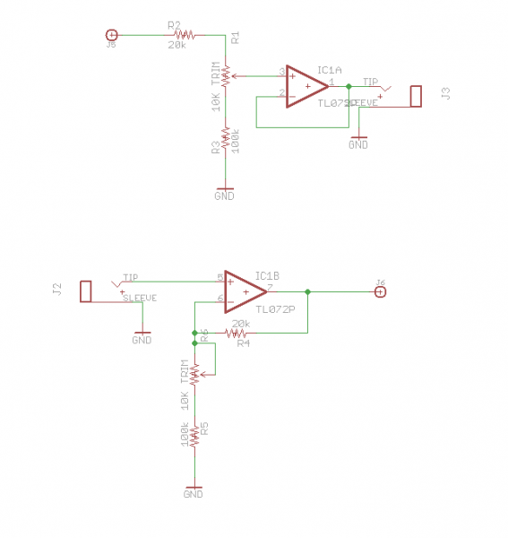
| elmegil wrote: | So this is what you're looking for then?
Be warned: this is off the top of my head, it is not tested, breadboarded, nor ever done before as I have no Buchla modules. But it's the circuitry to do what I suggested. If you were to get really really precise components, you could forego the trimmers, but in my opinion they're a safer way to get what you're after at whatever precision you can measure with your meter.
Edit: The outputs probably ought to have 1K resistors on them as well (between the op amp and the jack) for output protection. More important for non op-amp circuits, but still ought to be there generally. |
AWESOME!
This is exactly what I was looking for (even more, thank to your schematic).
I will breadboard and test: I wanted to understand what it needs for this kind of conversion (the logic) and with your help I am now able to do so.
It's the best way to start. I underxtand what you mean about the trimmers too. Cool.
Thank you very much elmegil. |
|
|
Back to top
|
|
|
elmegil
Joined: Mar 20, 2012
Posts: 2177
Location: Chicago
Audio files: 16
|
| Posted: Wed Feb 06, 2013 6:02 am Post subject:
|
|
|
As I look at it again, I can see an instance where the second circuit (1V -> 1.2V) could fail to work--if your 100k resistor is actually *higher* than 100k and the 20k is actually lower than 20k. You could use an 82K and a 20k or 25k trimmer to deal with that.
You're welcome as well  |
|
|
Back to top
|
|
|
rogerlatur
Joined: Dec 22, 2012
Posts: 118
Location: france
|
| Posted: Wed Feb 06, 2013 10:02 am Post subject:
|
|
|
| elmegil wrote: | | You could use an 82K and a 20k or 25k trimmer to deal with that. |
I'll check that. Thanx! |
|
|
Back to top
|
|
|
rogerlatur
Joined: Dec 22, 2012
Posts: 118
Location: france
|
| Posted: Mon Mar 25, 2013 1:52 pm Post subject:
|
|
|
I tested on breadboard your schematic. 1v to 1.2v.
I send 1v to the input and power on. When I set the 20k trimmer (because I am using a trimmer for 20k too) to 1.2v on the output, the input signal rises up to 2.18v.
I am sure I am doing something wrong. Here is what I did:
I replaced 20k with a 20k trimmer (cause it did not work either with normal 20k resistor).
Signal from TL072 pin 6 goes to Lug 1, Lug 2 goes to TL072 pin 7, Lug 3 goes to GND.
For the rest I did like on your schematic. Except that the 10k trimmer did not change anything. I remarked I bought a 100k trimmer instead of 10k, but as it did not change anything I disconnected from R6 on.
It was connected like this (R6 connections):
TL072 pin 6 to Lug 1.
Lug 1 and Lug 2 connected.
Lug 3 to R5 (100k resistor). |
|
|
Back to top
|
|
|
elmegil
Joined: Mar 20, 2012
Posts: 2177
Location: Chicago
Audio files: 16
|
| Posted: Mon Mar 25, 2013 2:21 pm Post subject:
|
|
|
It may be that there needs to be a resistor on the input. On an op amp, the + and - inputs are virtually tied together, so they will always show the same voltage.
Perhaps someone else with more experience could comment....I can see why this would be but I'm not familiar enough to say what the right way to deal with it might be.
Edit: I'm home now and re-reading, there are some definite problems with what you describe.
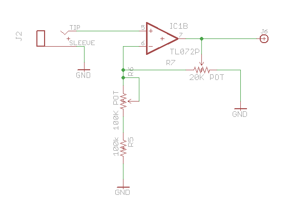
The third lug of the 20k pot should not go to ground 
Just to be sure, it sounds like what you've done is what I have in picture #1. For what you were trying to do, it should actually be like picture #2. I don't know that those pots that way would buy much though.
I honestly don't think that having the input change voltage is right. Are you sure you have a good TL072? Can you try a different one? Or even just use a TL071, though it has a different pinout (pin 2 is negative input, pin 3 is positive input, and pin 6 is output).
| Description: |
|
| Filesize: |
7.24 KB |
| Viewed: |
17436 Time(s) |
|
| Description: |
|
| Filesize: |
7.08 KB |
| Viewed: |
17436 Time(s) |

|
|
|
|
Back to top
|
|
|
rogerlatur
Joined: Dec 22, 2012
Posts: 118
Location: france
|
| Posted: Mon Mar 25, 2013 10:20 pm Post subject:
|
|
|
About my tests which didn't work:
I was testing the second schematic for 1v to 1.2v (with a 3.5" at the input and a banana at the output).
What I also did which is not mentionned was connecting TL072 pin4 to minus an pin8 to plus of power supply (15v).
I also tried with disconnecting trimmer from ground, but the 2 lugs were never connected during all my tests, so I will try now what you mentionned.
I will also test with new TL072 or TL071.
Thank you very much for your help! I will test this asap! |
|
|
Back to top
|
|
|
elmegil
Joined: Mar 20, 2012
Posts: 2177
Location: Chicago
Audio files: 16
|
| Posted: Mon Mar 25, 2013 11:19 pm Post subject:
|
|
|
I don't think I'd expect different results then.
The two lugs connected is just a convention. Ultimately it's the same circuit as using one side and the wiper and leaving the other side disconnected. |
|
|
Back to top
|
|
|
rogerlatur
Joined: Dec 22, 2012
Posts: 118
Location: france
|
| Posted: Wed Mar 27, 2013 3:15 pm Post subject:
|
|
|
Now the circuit is doing what it should. Nice!
With both trimmer set to their max, the outgoing voltage is 1.198v with an incoming of 1.0v.
I tested also with 91k resistor instead of the 100k and got 1.20v (and over if wished), so all is OK.
I will try also with a 20k resistor like you mentionned in your original post, as there is obviously no need for the 20k trimmer.
The problem I am now confronted is the following:
I set all like this. With an ingoing 1.0v at the 3.5" plug and an outgoing of 1.2v at the banana plug, I tuned 2 oscillators on an Eurorack system together as reference (they receive the signal unchanged), with 2 oscillators on Buchla (they receive the signal which went through the circuit, at the banana out).
All in tune. OK.
Then, I set the 1.0v signal to 2.0v. When I measure at the banana plug, it shows 2.4v.
For me it means the circuit is doing what it should.
But, the Buchla oscillators are not in tune with the Eurorack oscillators anymore!!!
And this is quite annoying! I thought this should be a correct way of testing, but something is not OK. And I don't understand what it is!
I tried with different oscillators, paired or not and always get the same untuned result when changing voltage (pitch).
With an incoming original signal set to 2.0v (2.4v at banana output) , I have to detune the Buchla oscillators to be again in tune with the Eurorack ones. |
|
|
Back to top
|
|
|
elmegil
Joined: Mar 20, 2012
Posts: 2177
Location: Chicago
Audio files: 16
|
| Posted: Thu Mar 28, 2013 5:40 am Post subject:
|
|
|
I would check the oscillators for their calibration.
Do 1V steps on the non-Buchla oscillators actually get you good solid octave steps?
Do 1.2V steps on the Buchla oscillators actually get you good solid octave steps?
If not, no type of 1V -> 1.2V conversion is going to keep you in tune. |
|
|
Back to top
|
|
|
rogerlatur
Joined: Dec 22, 2012
Posts: 118
Location: france
|
| Posted: Fri Apr 19, 2013 12:22 pm Post subject:
|
|
|
Forgot to update. Sorry!
The conversion is working fine. The problem is based on the oscillators not really in tune, the lower it goes within octaves. Good to know! |
|
|
Back to top
|
|
|
rogerlatur
Joined: Dec 22, 2012
Posts: 118
Location: france
|
| Posted: Sat Apr 20, 2013 11:53 am Post subject:
|
|
|
I took the 100k trimmer out of the 1v to 1.2v circuit here and got the same good results. Cool.
I have another question now here (I came to it after testing 12v to 9v possibilities for another project):
I tested the 1.2v to 1v conversion with one 2M resistor instead of a circuit.
And I got a regular 1v signal when I send 1.2v in, 2v when I send 2.4v etc etc.
I mean I get the same results for this attenuation, but only with a resistor, no other components.
Does it mean it is not ok because it does not offer any "protection"?
I mean I guess there is a good reason for making a circuit with trimmer, opAmp, resistors, and not simple a 2M resistor between 0v and +12v (I get 9v from one leg of the resistor, while the other leg is connected to 0v).
Thanx again for helping me understand all this here! |
|
|
Back to top
|
|
|
elmegil
Joined: Mar 20, 2012
Posts: 2177
Location: Chicago
Audio files: 16
|
| Posted: Sat Apr 20, 2013 1:53 pm Post subject:
|
|
|
| The drop from 1.2V to 1V with just a 2M resistor is going to be heavily dependent on your load. You might get away with it, but the op amps are there so that you get consistent results with any load. Not so much "protection" as it is consistency. |
|
|
Back to top
|
|
|
rogerlatur
Joined: Dec 22, 2012
Posts: 118
Location: france
|
| Posted: Sat Apr 20, 2013 2:33 pm Post subject:
|
|
|
| elmegil wrote: | | The drop from 1.2V to 1V with just a 2M resistor is going to be heavily dependent on your load. You might get away with it, but the op amps are there so that you get consistent results with any load. Not so much "protection" as it is consistency. |
I read something about "load" (wanted to check about reducing voltage via resistors once I breadboarded), but I confess I did not understand what it is?
+ For the 12v to 9v reduction I want to achieve (I was adviced to take a regulator, the easiest solution in fact) I read that one should first measure the load on the circuit when doing this with resistors instead, but I have no idea where/what to measure exactly. |
|
|
Back to top
|
|
|
elmegil
Joined: Mar 20, 2012
Posts: 2177
Location: Chicago
Audio files: 16
|
| Posted: Sat Apr 20, 2013 3:28 pm Post subject:
|
|
|
In the context you've given I'm not entirely sure what you're looking for.
What I mean by load is the equivalent resistance of the circuit. If the circuit (as seen by the 2M resistor) has equivalent resistance of 2M, then whatever voltage you input to the 2M resistor will be seen as half that voltage by the circuit, because you've created a voltage divider. If your load or equivalent is 10M, then the voltage divider will give you 1V for every 1.2V in to the 2M resistor.
So if I hook a circuit up to a battery, it will require a certain amount of current to drive the entire circuit. The "load" can refer either to the current, or to the equivalent resistance, depending on the context.
Given Ohm's law, V=IR, V would be the battery voltage, I would be the current, and R would be the equivalent resistance. So if I know V (and I should) and I (fairly easy to measure) then I can calculate R as V/I.
This would be true for any supply, not just a battery but that's the easiest way to explain, I think.
To measure the current you'd put an ammeter (or a multimeter set to its ammeter setting) in the circuit between the positive terminal of the power source and the rest of the "positive rail" of the circuit. Going back to the battery example, I'd replace the red wire from the battery holder with my multimeter, with the red probe at the battery and the black probe where the red wire would have connected to the circuit.
Does that make sense? |
|
|
Back to top
|
|
|
rogerlatur
Joined: Dec 22, 2012
Posts: 118
Location: france
|
| Posted: Sun Apr 21, 2013 3:34 am Post subject:
|
|
|
| elmegil wrote: | | If your load or equivalent is 10M, then the voltage divider will give you 1V for every 1.2V in to the 2M resistor. |
It makes sense!
I was not sure when I read that we first have to know the load value before reducing current via resistors...
| elmegil wrote: | To measure the current you'd put an ammeter (or a multimeter set to its ammeter setting) in the circuit between the positive terminal of the power source and the rest of the "positive rail" of the circuit. Going back to the battery example, I'd replace the red wire from the battery holder with my multimeter, with the red probe at the battery and the black probe where the red wire would have connected to the circuit.
Does that make sense? |
It does (this morning more than last night). Simple.
A main lack of know-how resides in the confusion I had at the beginning between voltage and current (honestly I thought "voltage+current" was "current" before I started with DIY projects and didn't know nothing about ohm law and so on).
It shows how important it is to know the main basics about electric current. And I really should now, as I did read quite a lot with very clear explanations too (starting with taking water as example and so on).
| elmegil wrote: | | The drop from 1.2V to 1V with just a 2M resistor is going to be heavily dependent on your load. You might get away with it, but the op amps are there so that you get consistent results with any load. Not so much "protection" as it is consistency. |
I will google on opAmp and read how these are done too. I know these have circuit inside, but I was not aware about this function for instance..
I will also check what a regulator is made of. As it seems that a simple 1.2v to 1v regulator would make it too (I know there is not such values for regulators, but I mean theoretically).
Precious help here, thank you very much! |
|
|
Back to top
|
|
|
rogerlatur
Joined: Dec 22, 2012
Posts: 118
Location: france
|
| Posted: Sun Apr 21, 2013 3:49 am Post subject:
|
|
|
The Wikipedia pages are quite informative:
• opAmp
• Voltage regulator |
|
|
Back to top
|
|
|
rogerlatur
Joined: Dec 22, 2012
Posts: 118
Location: france
|
| Posted: Sun Apr 21, 2013 4:12 am Post subject:
|
|
|
| rogerlatur wrote: | | ... it seems that a simple 1.2v to 1v regulator would make it too (I know there is not such values for regulators, but I mean theoretically). |
I checked the wikipedia page.
The answer also is yes, of course it would.
@ elmegil: your help here was precious.  |
|
|
Back to top
|
|
|
rogerlatur
Joined: Dec 22, 2012
Posts: 118
Location: france
|
| Posted: Sun Apr 21, 2013 5:18 am Post subject:
|
|
|
I opened a AC/DC power adapter and found the LM117T regulator inside which allows (depends what resistor we use with) to supply a 1.2v to 37v output range!
Seems like I was wrong thinking that there was no 1.2v regulator!
I don't know how precise these are + I will anyway ue the other method for 1.2v to 1v + only use a LM7809 for 12 or 15v to 9v, but I am discovering everyday something new.
What a fascinating electronic world! |
|
|
Back to top
|
|
|
rogerlatur
Joined: Dec 22, 2012
Posts: 118
Location: france
|
| Posted: Sun Apr 21, 2013 5:30 am Post subject:
|
|
|
For other friends here. I forgot to mention that I found the "handbook of operational amplifier applications" from Texas Instruments also very informative!
I mean mostly for now the circuits schematics, not the explanations which still confuse me very much. I didn't even understand the first lines of text!
But I will have to understand these, hence take more time with the readings.
| Quote: | | Consider the open loop amplifier used in the circuit of figure 10. Note that no current flows from the source into the inverting input - the summing point restraint derived in the previous section - hence, there is no voltage drop across RS and ES appears across the amplifier input. When ES is zero, the output is zero. If ES takes on any non-zero value, the output voltage increases to saturation, and the amplifier acts as a switch. |
summing point
restraint derived
voltage drop
increases to saturation
acts as a switch
Hey! Maybe I should learn english first?!
I am not asking here for any explanation, I will have to do this by my own.
And I know I can ask on the forum if I miss something precise, but I will first spend some more time and do some more research + cross-infos... Otherway I would have to ask every 2 minutes!!!
Last edited by rogerlatur on Sun Apr 21, 2013 5:55 am; edited 1 time in total |
|
|
Back to top
|
|
|
elmegil
Joined: Mar 20, 2012
Posts: 2177
Location: Chicago
Audio files: 16
|
| Posted: Sun Apr 21, 2013 5:54 am Post subject:
|
|
|
You're quite welcome
And thanks for that link Roger, that looks very useful. |
|
|
Back to top
|
|
|
|

 Forum index » DIY Hardware and Software » The layout factory