| Author |
Message |
tysseng
Joined: Apr 14, 2013
Posts: 13
Location: Norway
|
 Posted: Sun Apr 14, 2013 1:07 pm Post subject:
Multifaceted response curve from linear CV Posted: Sun Apr 14, 2013 1:07 pm Post subject:
Multifaceted response curve from linear CV
Subject description: I am having trouble creating a circuit that generates a CV voltage with different components |
  |
|
Hi!
First of all let me say that I'm an amateur when it comes to analog design, so don't be too hard on me 
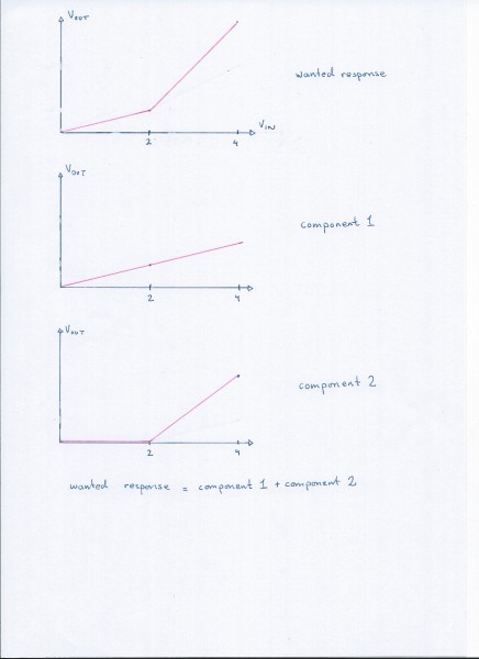
I am trying to create a circuit that transform a linear CV into a curve with several components. E.g, from 0 to 2V the input should be attenuated by a factor of 2, from 2 to 5 it should be attenuated by a factor of 1.5 or similar. The actual numbers are not important but the principle is.
See my attachments for a drawing of the response I want.
My approach to this is to make two separate amplifier parts. One that generates the first part (from 0 to 2v) and one that generates the second part, and thus is 0v untill the input voltage reaches 2V. I will then sum up the result to get the intended response
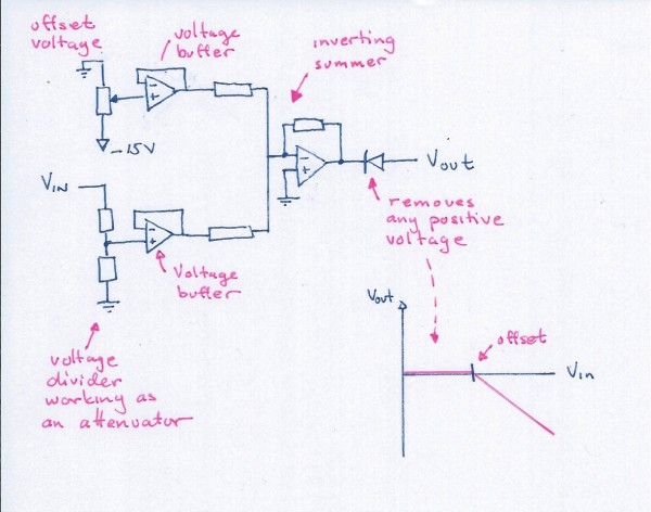
The first part is easy. For the second part, my idea is to create a circuit that attenuates the signal by the factor I want, then to add a negative voltage to offset the 0v crossing point so that V-out is 0v when V-in is 2v. Finally I add a diode to reject the negative part so that the response is 0 in the range 0 to 2v. (in my circuit diagram this diode does the oposite, it rejects positive voltages, since I am using an inverting summer).
The circuit I have drawn up works as intended (at fairly low frequencies, but that's ok, the input voltage is controlled using either an LFO or a pot, so high frequencies are not a problem.
What IS a problem however, is that when i try connecting this circuit to an additional summer, or even to a voltage buffer, it does not act very well.
How would I go about connecting this circuit to a summer - or if that is not possible, are there other ways of rejecting the negative/positive part of a signal without using a diode?
--
cheers,
Joakim
| Description: |
| Wanted response curve, with my suggested approach of adding two separate curves. |
|
| Filesize: |
742.25 KB |
| Viewed: |
124 Time(s) |
| This image has been reduced to fit the page. Click on it to enlarge. |
|
| Description: |
| My attempt at making a circuit that generates the second part of the response curve |
|
| Filesize: |
266.27 KB |
| Viewed: |
127 Time(s) |
| This image has been reduced to fit the page. Click on it to enlarge. |
|
|
|
|
Back to top
|
|
 |
gdavis
Joined: Feb 27, 2013
Posts: 359
Location: San Diego
Audio files: 1
|
| Posted: Sun Apr 14, 2013 2:16 pm Post subject:
|
|
|
Your desired response looks like a linear approximation of an exponential. Does it really need to be two linear segments or could you use an exponential converter? Designs for the latter are pretty easy to find.
_________________
My synth build blog: http://gndsynth.blogspot.com/ |
|
|
Back to top
|
|
|
Scott Stites
Janitor


Joined: Dec 23, 2005
Posts: 4127
Location: Mount Hope, KS USA
Audio files: 96
|
|
|
Back to top
|
|
|
Scott Stites
Janitor
Joined: Dec 23, 2005
Posts: 4127
Location: Mount Hope, KS USA
Audio files: 96
|
|
|
Back to top
|
|
|
elmegil

Joined: Mar 20, 2012
Posts: 2177
Location: Chicago
Audio files: 16
|
| Posted: Sun Apr 14, 2013 11:22 pm Post subject:
|
|
|
You didn't make a batman logo, Scott!  |
|
|
Back to top
|
|
|
Scott Stites
Janitor
Joined: Dec 23, 2005
Posts: 4127
Location: Mount Hope, KS USA
Audio files: 96
|
| Posted: Mon Apr 15, 2013 5:36 am Post subject:
|
|
|
I'm Batman!
_________________
My Site |
|
|
Back to top
|
|
|
tysseng
Joined: Apr 14, 2013
Posts: 13
Location: Norway
|
| Posted: Mon Apr 15, 2013 11:48 am Post subject:
|
|
|
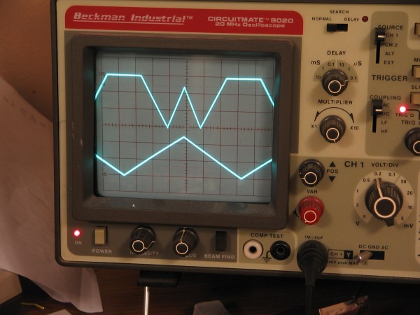
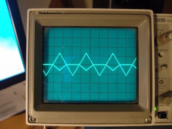
Wow, thanks for the quick replies, I am stunned Scott: That was exactly what I was looking for. I tried it out, it works perfectly.
gdavis: It looks quite like an exponential function, and I did think about approximating part of it using an exponential function. The real curve goes much further to the right before it suddenly bends upwards. I did read up on antilogarithmic amplifiers using transistors, but was a bit set off by the thermal compensation problem. However, since you called it an exponential converter (I hadn't heard that term before, just antilog or exponential amplifier), I struck gold (for me) right after googling it, with MiK-Music's article https://plus.google.com/107231411209962227230/posts/C8iVtXKzvet
Thanks for all your help. Here is my first try:
| Description: |
|
| Filesize: |
2.37 MB |
| Viewed: |
128 Time(s) |
| This image has been reduced to fit the page. Click on it to enlarge. |
|
|
|
|
Back to top
|
|
|
gdavis
Joined: Feb 27, 2013
Posts: 359
Location: San Diego
Audio files: 1
|
| Posted: Mon Apr 15, 2013 12:20 pm Post subject:
|
|
|
Well I'd never seen the ideal diode circuit before, so I learned something too. That things pretty cool, I spiced it up and it really works great!
_________________
My synth build blog: http://gndsynth.blogspot.com/ |
|
|
Back to top
|
|
|
Scott Stites
Janitor
Joined: Dec 23, 2005
Posts: 4127
Location: Mount Hope, KS USA
Audio files: 96
|
| Posted: Mon Apr 15, 2013 12:44 pm Post subject:
|
|
|
Copyright that waveform ASAP. Then you can sell to AAA as a new, improved logo. 
Bruce Wayne sent me a cease and desist. 
_________________
My Site |
|
|
Back to top
|
|
|
corex

Joined: Mar 02, 2010
Posts: 114
Location: Las Vegas
|
| Posted: Wed Apr 17, 2013 4:52 pm Post subject:
|
|
|
| This is a very cool circuit... I should try it out. The possibilities are interesting. |
|
|
Back to top
|
|
|
|

 Forum index » DIY Hardware and Software