| Author |
Message |
axg20202
Joined: Mar 11, 2013
Posts: 20
Location: London
|
 Posted: Tue May 14, 2013 9:43 am Post subject: Posted: Tue May 14, 2013 9:43 am Post subject:
|
  |
|
Thanks for the detailed reply. I guess I will just have to experiment with some switches and resistor networks. By the way, the tip re the guitar hero whammy bar was a good one. I picked up 5 (yeah, 5...overkill but they were sold in 5s) faulty customer returns on e-bay for very little. Seems to work well. I toyed with the idea of going the breath control route (I have a Yamaha S80, which has a BC input), but the cost of the controller put me off - Yamaha BC3s are as rare as rocking horse 5h1t as they aren't made any more. Other options are costly too. So, a lever it is. I'm also seeing if I can integrate a foot controller somehow.
Thanks for sharing your notes/videos - they have helped a lot. |
|
|
Back to top
|
|
 |
yusynth

Joined: Nov 24, 2005
Posts: 1314
Location: France
|
| Posted: Sun Jun 02, 2013 2:45 am Post subject:
|
|
|
Hi friends
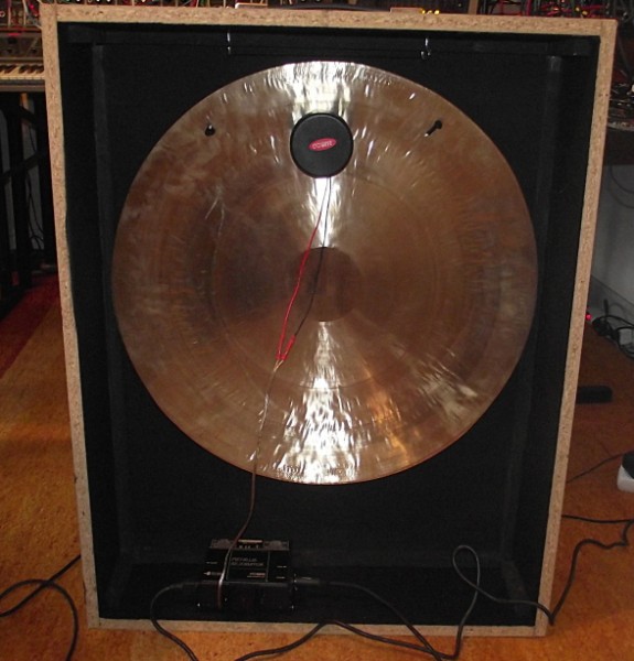
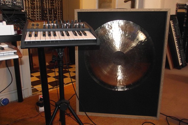
Yesterday I received the Eowave Metalik Resonator, an ideal complement for my ondes Martenot.
Here are some photos of the resonator. Note that the Resonator is normally sold by Eowave with a tolex finish for the cabinet but I asked them send me the raw cabinet such that I can cover it myself with wood veneer matching that of my ondes Martenot
| Description: |
| Seen from the back, one can see the compressor motor attached to the Tam foil in its upper part, and the 50W power amplifier on the bottom |
|
| Filesize: |
185.38 KB |
| Viewed: |
1278 Time(s) |
| This image has been reduced to fit the page. Click on it to enlarge. |
|
| Description: |
| Frontview : the MiniBrute on the left gives an idea of the size of the resonator. It's the bigger model. |
|
| Filesize: |
382.45 KB |
| Viewed: |
1088 Time(s) |
| This image has been reduced to fit the page. Click on it to enlarge. |
|
_________________
Yves |
|
|
Back to top
|
|
|
v-un-v
Janitor


Joined: May 16, 2005
Posts: 8933
Location: Birmingham, England, UK
Audio files: 11
G2 patch files: 1
|
| Posted: Sun Jun 02, 2013 4:03 pm Post subject:
|
|
|
I just read about this Finnish guy on Synthtopia who's made an Ondes Martenot style modification to the Korg Monotron. Nice video too!
http://electronicmelodist.blogspot.co.uk
_________________
ACHTUNG!
ALLES TURISTEN UND NONTEKNISCHEN LOOKENPEEPERS!
DAS KOMPUTERMASCHINE IST NICHT FÜR DER GEFINGERPOKEN UND MITTENGRABEN! ODERWISE IST EASY TO SCHNAPPEN DER SPRINGENWERK, BLOWENFUSEN UND POPPENCORKEN MIT SPITZENSPARKSEN.
IST NICHT FÜR GEWERKEN BEI DUMMKOPFEN. DER RUBBERNECKEN SIGHTSEEREN KEEPEN DAS COTTONPICKEN HÄNDER IN DAS POCKETS MUSS.
ZO RELAXEN UND WATSCHEN DER BLINKENLICHTEN. |
|
|
Back to top
|
|
|
axg20202
Joined: Mar 11, 2013
Posts: 20
Location: London
|
| Posted: Mon Jun 03, 2013 5:28 am Post subject:
|
|
|
Re trill buttons: | axg20202 wrote: | | Thanks for the detailed reply. I guess I will just have to experiment with some switches and resistor networks. |
OK, I'm making progress on my ondes controller. But today I decided to have a think about how to implement trill buttons into the voltage offset arrangement, culminating in some calculations that are almost certainly incorrect  
Here goes:
1v per octave.
Increase of 1/12v (0.083v) gives a semitone rise in pitch
Increase of 1/6v (0.167v) gives a whole tone rise in pitch
Using the offset circuit mentioned earlier, a 100k linear pot gives the 0-10v range of offset voltage values. So, a 50k setting gives 5v offset.
If so, then 0.83k gives 0.083v offset (semitone) and 1.67k gives 0.167v offset (whole tone).
Sooo, if I wire in momentary switches that insert/remove either 830R or 167R in series with the 100k pot, I should get a semitone or whole tone increase in pitch....
Now, the above is probably total testicles, so if anyone can chime in that would be great!  |
|
|
Back to top
|
|
|
Infrablue
Joined: Dec 29, 2011
Posts: 131
Location: Utah
|
| Posted: Sun Jun 09, 2013 2:53 am Post subject:
|
|
|
| yusynth wrote: | Hi friends
Yesterday I received the Eowave Metalik Resonator, an ideal complement for my ondes Martenot.
Here are some photos of the resonator. Note that the Resonator is normally sold by Eowave with a tolex finish for the cabinet but I asked them send me the raw cabinet such that I can cover it myself with wood veneer matching that of my ondes Martenot |
Just incredible! I saw these and it's so tempting to get one!
How amazing you have an actual Ondes Martenot as well! Any performance vids of it? Very neat stuff. Thanks for sharing this. |
|
|
Back to top
|
|
|
Infrablue
Joined: Dec 29, 2011
Posts: 131
Location: Utah
|
| Posted: Sun Jun 09, 2013 2:55 am Post subject:
|
|
|
I just randomly found this as well on youtube!
I really like it!! We done!!
And check out his expression lever.... simple as can be, and sounds great.
here's the video: http://www.youtube.com/watch?v=YpDvUq1EvDY |
|
|
Back to top
|
|
|
yusynth
Joined: Nov 24, 2005
Posts: 1314
Location: France
|
| Posted: Sun Jun 09, 2013 3:11 am Post subject:
|
|
|
| Infrablue wrote: | | How amazing you have an actual Ondes Martenot as well! Any performance vids of it? Very neat stuff. Thanks for sharing this. |
Well, living in France helps a lot to find ondes Martenot, although these are quite rare and very much sought after. My ondes Martenot (built in the 60s therefore it's a tube model) are working fine but the woodwork which is in a very used and thorn state. I hope to have finished restoring the woodwork by mid-summer.
_________________
Yves |
|
|
Back to top
|
|
|
tojpeters
Joined: Feb 04, 2013
Posts: 22
Location: cali (far north)
|
| Posted: Wed Jun 12, 2013 3:16 pm Post subject:
|
|
|
| Anyone have a suggestion for a transducer for a D.I.Y. version? I really know nothing about transducers, so even specs to look for or places that carry a selection would be very helpful. My controller project has made good progress,everything is tested and I just need a few more pieces of wood to finish it. |
|
|
Back to top
|
|
|
tojpeters
Joined: Feb 04, 2013
Posts: 22
Location: cali (far north)
|
| Posted: Wed Jun 26, 2013 7:05 am Post subject:
|
|
|
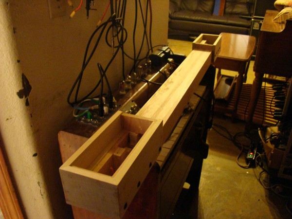
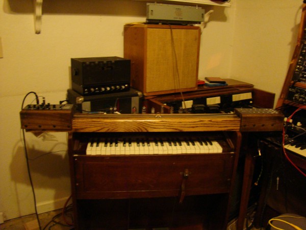
just need to sand/finish the wood, replace a pot that i managed to destroy, and build a couple A/R generators for the right side control panel. everything is tested, just need to put it all together. I found the transducers i need, i need a gong now. I'm also mounting a couple of them on the soundboards of the reed organ this is built on. Also need to re-tune the keyboard as i switched from +/- 12v to +/- 15v. Probably wait on that as it only does about 20 keys and i think that can be improved. i need to be able to hold the voltages [0-12VDC and 0-150VDC)after key up until the next key down to really make it nice.
| Description: |
|
| Filesize: |
976.07 KB |
| Viewed: |
1044 Time(s) |
| This image has been reduced to fit the page. Click on it to enlarge. |
|
| Description: |
|
| Filesize: |
954.17 KB |
| Viewed: |
1023 Time(s) |
| This image has been reduced to fit the page. Click on it to enlarge. |
|
|
|
|
Back to top
|
|
|
tojpeters
Joined: Feb 04, 2013
Posts: 22
Location: cali (far north)
|
| Posted: Wed Jul 17, 2013 4:13 pm Post subject:
|
|
|
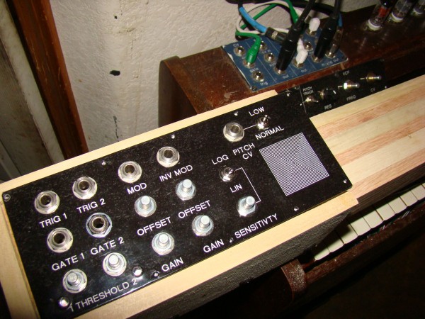
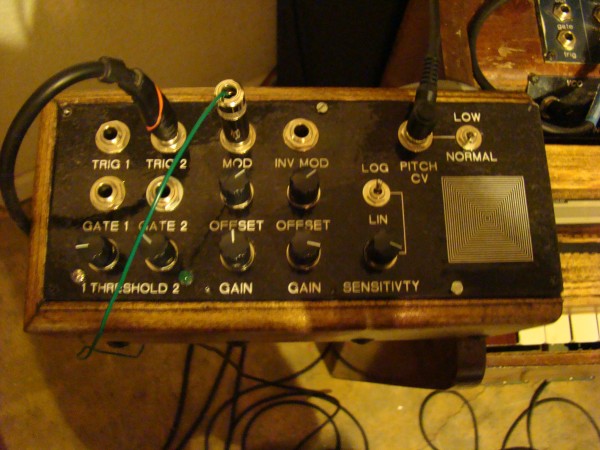
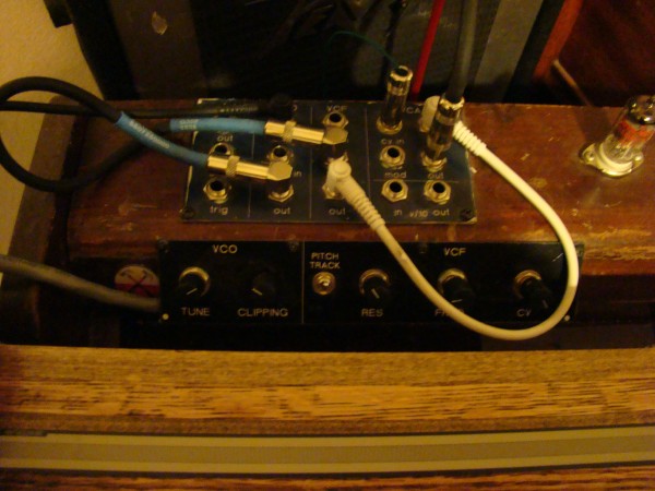
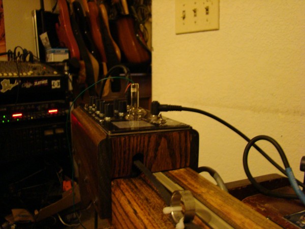
everything works. now i need to add position markers. will add 2 ADSRs in the future.
| Description: |
|
| Filesize: |
1003.09 KB |
| Viewed: |
958 Time(s) |
| This image has been reduced to fit the page. Click on it to enlarge. |
|
| Description: |
|
| Filesize: |
942.03 KB |
| Viewed: |
833 Time(s) |
| This image has been reduced to fit the page. Click on it to enlarge. |
|
| Description: |
|
| Filesize: |
932.29 KB |
| Viewed: |
917 Time(s) |
| This image has been reduced to fit the page. Click on it to enlarge. |
|
| Description: |
|
| Filesize: |
934.91 KB |
| Viewed: |
857 Time(s) |
| This image has been reduced to fit the page. Click on it to enlarge. |
|
|
|
|
Back to top
|
|
|
mosc
Site Admin

Joined: Jan 31, 2003
Posts: 18198
Location: Durham, NC
Audio files: 213
G2 patch files: 60
|
| Posted: Thu Jul 18, 2013 10:46 am Post subject:
|
|
|
Beautiful work, tojpeters.
_________________
--Howard
my music and other stuff |
|
|
Back to top
|
|
|
Infrablue
Joined: Dec 29, 2011
Posts: 131
Location: Utah
|
| Posted: Wed Aug 28, 2013 2:01 am Post subject:
|
|
|
| tojpeters... this is looking great. Can't wait to hear it! |
|
|
Back to top
|
|
|
tojpeters
Joined: Feb 04, 2013
Posts: 22
Location: cali (far north)
|
| Posted: Wed Aug 28, 2013 8:46 am Post subject:
|
|
|
| thanks. i was going to post video but this thread kinda died out. it excels at the things one would expect- vibrato, slides. not as good at fast playing,takes time to move up an octave or two. |
|
|
Back to top
|
|
|
Buxi

Joined: Oct 01, 2018
Posts: 2
Location: Bordeaux (France)
|
|
|
Back to top
|
|
|
patmcm
Joined: Jan 08, 2013
Posts: 1
Location: Montreal, QC
|
| Posted: Mon Oct 01, 2018 12:22 pm Post subject:
|
|
|
C'est génial! Félicitations - j'aimerais bien si vous pouvez parler de comment vous avez réussi ce beau instrument - quelles sont les modules Doepfer que vous avez utilisé? Merci de partager vos impros - vraiment super! |
|
|
Back to top
|
|
|
Buxi
Joined: Oct 01, 2018
Posts: 2
Location: Bordeaux (France)
|
| Posted: Sun Oct 07, 2018 5:32 am Post subject:
|
|
|
Comme vous le voyez, j'ai utilisé des modules Doepfer.
- Un module VCO A110-1, quatre formes d'ondes en sortie
- Un module Mixer A138, pour mélanger les formes d'ondes du VCO
- Un module noise A118, dont la sortie white entre en entrée CV2 du VCO pour générer un bruit blanc contrôlable (et faire des bruits de vent, de vague etc)
- la sortie du mixer va vers l'entrée de la touche d'expression.
- la sortie de la touche d'expression est branchée en entrée d'un second module mixer A138, sur lequel est aussi branché la sortie "colored" du module noise, ainsi qu'un module radio que j'ai fabriqué et qui est piloté par la sortie "random" du module noise (ce module radio DIY est une radio FM/AM qui change de fréquence en fonction d'une entrée CV).
- La sortie du second module mixer A138 est branchée sur un module spring reverb A199
Voici les schémas électroniques, ils sont très rudimentaires.
Le clavier :

Le clavier est monté sur des rails de tiroir et maintenu par des ressors.
Electroniquement, c'est un pont diviseur de tension. En entrée de la chaine de résistances, il y a un trimer qui permet de régler le niveau d'entrée. En sortie, de la chaine de résistance un autre trimer et une photo-résistance. Le réglage des deux trimers permet de régler la tension pour que chaque touche délivre un CV correspondant. La photorésistance est fixée sous le clavier, elle suis son mouvement.
Fixe au châssis, une LED éclaire la photorésistance. Lorsque le clavier bouge, la valeur de la photorésistance augmente ou diminue, ce qui crée l'effet de vibrato.


La bague :

Pour le jeu à la bague, j'utilise un potentiomètre multitour.
La poulie est légèrement plus grande que ce qu'il faudrait pour la longueur de fil. Cela me permet de régler la note la plus basse que je peux atteindre avec la bague. Le potentiomètre est branché en pont diviseur de tension avec en sortie de la résistance totale du potentiomètre, un trimer permettant d'accorder la tessiture de la bague en fonction de l'étendue du clavier.

Le sélecteur Clavier/Bague :
La sortie du clavier et la sortie de la bague sont dirigée vers un sélecteur permettant de choisir le type de contrôle. La sortie du sélecteur va vers une l'entrée CV du VCO.
Elle est également connectée à l'entrée analogique d'un Arduino qui a trois fonctions :
- allumer une LED lorsque la tension "lue" correspond à un Do, ce qui me permet de régler facilement Clavier et Bague
- Couper au moyen d'un optocoupleur MOC3020 lorsque la valeur lue correspond au fait de ne pas appuyer sur une touche du clavier (et éviter de générer sans arrêt la note la plus basse du VCO)
- allumer la LED de la touche d'expression (je vais y venir) afin de limiter les bruit de "mise en son" généré lorsque le MOC3020 se ferme et permet l'arrivée du son.

La touche d'expression :
La touche d'expression est montée sur un ressors qui fait qu'elle remonte dès qu'on appuie plus dessus. Sous cette touche se trouve une LED. Deux photorésistances en série forment un pont diviseur de tension. La LED est commandée par un Arduino et fonctionne seulement lorsque la valeur CV lue par l'Arduino correspond soit au sélecteur sur mode "Bague", soit au sélecteur sur mode "Clavier" avec touche enfoncée.
Lorsque la touche est en haut et qu'une valeur CV satisfaisante est lue, la LED éclaire la première photorésistance, l'autre photorésistance n'est pas éclairée. Le volume sonore est à zéro. Plus on enfonce la touche d'expression, plus la LED éclaire la seconde photorésistance et moins la première photorésistance est éclairée. Le volume sonore augmente.
 |
|
|
Back to top
|
|
|
|

 Forum index » DIY Hardware and Software

