| Author |
Message |
Joelelectro
Joined: Oct 01, 2014
Posts: 9
Location: Xalapa
|
 Posted: Wed Oct 01, 2014 9:40 am Post subject:
LM13700 filter Posted: Wed Oct 01, 2014 9:40 am Post subject:
LM13700 filter
Subject description: Probe a filter with LM13700 |
  |
|
The other day i buy LM13700 but i never used a OTA but i want learn how to use i read the datasheet i decided to prove and i decide to build the low pass filter.


I dont understand what i need to do with AMP bias input only send to the capacitor with buffer input to the ground. Its not necesary to inject to current in AMP bias output. My other question whats the meaning "Vc" in the first picture next to resistence 30k. I need to inject voltage
I'm amateur XD... |
|
|
Back to top
|
|
 |
PHOBoS

Joined: Jan 14, 2010
Posts: 5599
Location: Moon Base
Audio files: 705
|
 Posted: Wed Oct 01, 2014 11:13 am Post subject:
Re: LM13700 filter Posted: Wed Oct 01, 2014 11:13 am Post subject:
Re: LM13700 filter
Subject description: Probe a filter with LM13700 |
  |
|
 
| Joelelectro wrote: | | I dont understand what i need to do with AMP bias input only send to the capacitor with buffer input to the ground. Its not necesary to inject to current in AMP bias output. My other question whats the meaning "Vc" in the first picture next to resistence 30k. I need to inject voltage |
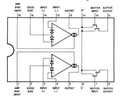
you need to connect the output (pin 5/12) to the buffer input (pin 7,10) with a capacitor to ground.
then you can inject the voltage into Vc which is a resistor attached to the AMP bias input.
An OTA is actually current controlled not voltage controlled but there are other people here on the forum
who know a lot more about that then me.
_________________
"My perf, it's full of holes!"
http://phobos.000space.com/
SoundCloud BandCamp MixCloud Stickney Synthyards Captain Collider Twitch YouTube |
|
|
Back to top
|
|
 |
Joelelectro
Joined: Oct 01, 2014
Posts: 9
Location: Xalapa
|
 Posted: Wed Oct 01, 2014 11:18 am Post subject:
Re: LM13700 filter Posted: Wed Oct 01, 2014 11:18 am Post subject:
Re: LM13700 filter
Subject description: Probe a filter with LM13700 |
  |
|
| PHOBoS wrote: |  
| Joelelectro wrote: | | I dont understand what i need to do with AMP bias input only send to the capacitor with buffer input to the ground. Its not necesary to inject to current in AMP bias output. My other question whats the meaning "Vc" in the first picture next to resistence 30k. I need to inject voltage |
you need to connect the output (pin 5/12) to the buffer input (pin 7,10) with a capacitor to ground.
then you can inject the voltage into Vc which is a resistor attached to the AMP bias input.
An OTA is actually current controlled not voltage controlled but there are other people here on the forum
who know a lot more about that then me. |
approximately how much voltage inject into Vc?
now i think 5v ? exist specific voltage |
|
|
Back to top
|
|
 |
blue hell
Site Admin

Joined: Apr 03, 2004
Posts: 24083
Location: The Netherlands, Enschede
Audio files: 278
G2 patch files: 320
|
 Posted: Wed Oct 01, 2014 11:37 am Post subject: Posted: Wed Oct 01, 2014 11:37 am Post subject:
|
  |
|
Not more than 15V or the OTA may blow ... the voltage determines the filter frequency .. or actually it is the current that flows as a result of the voltage applied which controls it.
_________________
Jan
also .. could someone please turn down the thermostat a bit.
 |
|
|
Back to top
|
|
 |
Joelelectro
Joined: Oct 01, 2014
Posts: 9
Location: Xalapa
|
 Posted: Wed Oct 01, 2014 7:53 pm Post subject:
Dude Posted: Wed Oct 01, 2014 7:53 pm Post subject:
Dude
Subject description: Lm13700 |
  |
|
| Blue Hell wrote: | | Not more than 15V or the OTA may blow ... the voltage determines the filter frequency .. or actually it is the current that flows as a result of the voltage applied which controls it. |
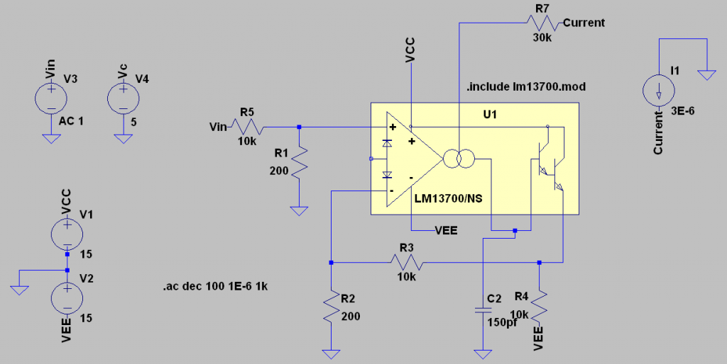
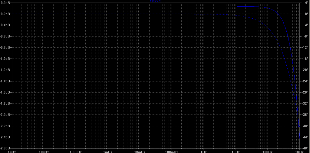
I try to make the simulate the circuit and design the example of datasheet Voltage Controlled Low-Pass Filter i take the parameters and formulate for the low pass filter:
fo=(RA*gm)/((R+RA)2*pi*C)
The paramethers are for the:
RA=200ohm
R=100k
C=150pf
IABC=3e-6
The datasheet make reference where gm ≈ 19.2 IABC at 25°C.
and i Supposed:
fo=(200*19.2*3e-6)/((100k+200)*2pi*150pf)
and my result=122.05 hz
In the simulate i take the reference
5 μA ≤ IABC ≤ 500 μA
[img] [/img] [/img]
[img]
[/img]
My question how i can identificated my filter is corred i use the elements for the desing of the datasheet, only i can see the response. |
|
|
Back to top
|
|
 |
Joelelectro
Joined: Oct 01, 2014
Posts: 9
Location: Xalapa
|
 Posted: Thu Oct 02, 2014 2:44 pm Post subject:
Re: Dude Posted: Thu Oct 02, 2014 2:44 pm Post subject:
Re: Dude
Subject description: Lm13700 |
  |
|
| Joelelectro wrote: | | Blue Hell wrote: | | Not more than 15V or the OTA may blow ... the voltage determines the filter frequency .. or actually it is the current that flows as a result of the voltage applied which controls it. |
I try to make the simulate the circuit and design the example of datasheet Voltage Controlled Low-Pass Filter i take the parameters and formulate for the low pass filter:
fo=(RA*gm)/((R+RA)2*pi*C)
The paramethers are for the:
RA=200ohm
R=100k
C=150pf
IABC=3e-6
The datasheet make reference where gm ≈ 19.2 IABC at 25°C.
and i Supposed:
fo=(200*19.2*3e-6)/((100k+200)*2pi*150pf)
and my result=122.05 hz
In the simulate i take the reference
5 μA ≤ IABC ≤ 500 μA
[img] [/img] [/img]
[img]
[/img]
My question how i can identificated my filter is corred i use the elements for the desing of the datasheet, only i can see the response. |
HOW KNOWS THE TOPOLOGY FOR LM13700 WITH OTA'S NOT WITH TRANSISTOR OR OPAMS, I REFER THE ANILYSIS WITH BLOCK ABOUT THE OTA |
|
|
Back to top
|
|
 |
emmaker
Joined: Aug 10, 2007
Posts: 12
Location: Portland, OR
|
 Posted: Thu Oct 02, 2014 8:21 pm Post subject: Posted: Thu Oct 02, 2014 8:21 pm Post subject:
|
  |
|
Several things are a problem in the simulation.
First the input resistor and feedback resistor in the simulation are 10K and not 100K.
As mentioned these are really current controlled amplifiers. The control currernt Amp Bias Input or Iabc should be limited to 2ma MAX! Again as mentioned above if you exceed this it will FRY/DAMAGE the chip. It's really easy to do this so be careful with the Iabc and buy a few extra chips when you get them.
The filter in the data sheet says Vc which stands for voltage control but Iabc wants current. That's where that 30K resistor comes in. It forms a current to voltage converter. So you are putting a current into a voltage to current converter so things are going to be off (which is refereneced to ground, see below). So either remove the resistor and use a current or leave it in and use a voltage.
Iabc is relative to V- and not ground so that needs to be keep in mind. You can use ohms law (V=I*R) to figure out what the control current is with a voltage and resistor value.
Iabc = (Vc - (V- + 0.6) ) / Rabc (0.6 is from a diode drop between Iabc and V-)
So for 10V Vc, 30K for Rabc and +/-15V power supply.
(10 - (-15 + 0.6)) / 30000 = 24.4 / 30000 = 0.0008333 amps = 0.83 ma
Lastly look at Figure 16 in the data sheet. You want the input on the + and - input to be about 10mv peek to peek for 0.1% distortion. So the input resistors form a divider with a ratio of (200 / 100200) ~ 0.002. So for Vin * ratio = 0.01, Vin = 0.01 / 0.002 = 5. So you want Vin to be 5V peek to peek. |
|
|
Back to top
|
|
 |
|

