| Author |
Message |
wackelpeter
Joined: May 05, 2013
Posts: 461
Location: germany
Audio files: 10
|
 Posted: Sat Jul 19, 2014 7:30 am Post subject:
Re: sine wave Posted: Sat Jul 19, 2014 7:30 am Post subject:
Re: sine wave |
  |
|
| messerschmitt twin wrote: | | hi, I built the TH 555 vco on stripboard, from the circuit diagram,everything works except the sine wave, I just get a triangle wave, so I bread boarded the LM13700 sine shaper and fed the triangle from pin 14 of IC3, but my breadboarded layout just produces a triangle output as well? Any ideas would be most wellcomed. |
the Output of the sine is set via trimmer R24... which rounds it up as a sine the more you turn it in the one direction it goes more into a sine wave including a reducing of the Amplitude and in the other direction the amplitude rises and the waveform turns more into a triangle...
Trimmer R38 Centers the sine around Zero Volts/ground...
try playing with the values of R27 and the trimmer R24...
maybe the total of those both resistors is a bit to low or to high to achieve the best result...
also check the values of R3, R26 and R34
either the Input on Pin13 or the Input bias at pin1 seem to be to high i guess
if your Amplitude is a bit weaker than the 3 others try reducing R34 .
i have used 56K insetad of 100K so my sine is at the same Level as the triangle and 1,5VP/P above the square and ramp...
i also had to Change the values of some other resistors to get all signals at same Levels... for pulse i changed R8 from 1K8 to 2K7 and for the ramp i changed R33 from 100K to 120K...
hope this helps a bit.. otherwise just wait until one of the "wise men" of this Forum answers... 
P.S. nice to know i'm not the only one still drilling holes in stripboards... 
P.P.S. just forgot maybe your triangle signal at pin 14 of IC3 from which the sine is generated is maybe to high... what amplitude do you get there?
_________________
https://soundcloud.com/bastian-j |
|
|
Back to top
|
|
 |
messerschmitt twin
Joined: Jul 19, 2014
Posts: 6
Location: leicester, england
|
| Posted: Sat Jul 19, 2014 7:41 am Post subject:
|
|
|
| thanks for your help, i double checked the values, my other waveforms are fine, as is the triangle coming out of the sine wave shaper lol, maybe i'm not adjusting it properly if R27 and R34 can produce a triangle output. I have managed to blow a few LM13700's in the past messing with the inputs on pins 1 and 16, i'll have another try later, thanks again. |
|
|
Back to top
|
|
|
wackelpeter
Joined: May 05, 2013
Posts: 461
Location: germany
Audio files: 10
|
| Posted: Sat Jul 19, 2014 8:02 am Post subject:
|
|
|
no Problem at all normally i'm the the one crying for help... but just finished 2 of them last week...
did a mistake in my previous post
i meant not pin 1 of the lm13700 i meant pin 16 of course...
to me it Looks like one of These just get to much Input so that the sine is folded into a triangle...
Matthias/Fonik pointed me on the value of R27 he suggested to lower R27 A bit think it was 33K or 27K and instead Exchange trimmer R24 with an 47 or 50K one...
_________________
https://soundcloud.com/bastian-j |
|
|
Back to top
|
|
|
messerschmitt twin
Joined: Jul 19, 2014
Posts: 6
Location: leicester, england
|
| Posted: Sat Jul 19, 2014 8:11 am Post subject:
|
|
|
| just had another look, using a 50K preset and adjusting it makes no difference to the triangle, also its about 15V peak to peak, yes knew you meant pin 16, i'll try lowering the 39k resistor, thanks again. |
|
|
Back to top
|
|
|
wackelpeter
Joined: May 05, 2013
Posts: 461
Location: germany
Audio files: 10
|
| Posted: Sat Jul 19, 2014 8:30 am Post subject:
|
|
|
15V PP seems to be too much... don't remember really but i think it was supposed to be 6-8 V PP at each signal Output...
do you measure these 15V PP at the sine or at the real/destinated triangle Output?
Maybe also have a look at this thread beginning on page 3 there Thomas gave some hints concerning the sine wave
_________________
https://soundcloud.com/bastian-j |
|
|
Back to top
|
|
|
messerschmitt twin
Joined: Jul 19, 2014
Posts: 6
Location: leicester, england
|
| Posted: Sat Jul 19, 2014 8:37 am Post subject:
|
|
|
| lowered it to 27K still no change, swapped LM13700 and its now a perfect sine, just tweaking it now with the presets, so was down to a partially working LM13700, thanks for your help. |
|
|
Back to top
|
|
|
wackelpeter
Joined: May 05, 2013
Posts: 461
Location: germany
Audio files: 10
|
| Posted: Sat Jul 19, 2014 8:47 am Post subject:
|
|
|
nice to hear that it works now... great VCO you simply can't live wtihout one and when you have one you want more... 
i think i will go for 2 more as i now have my stripboard layout as a "master" the second one got finished much more faster so will be the next ones...
if you just ahev one half of that LM13700 working maybe include that in an VCA i've finished yesterday...
http://hem.bredband.net/bersyn/VCA/lm13600%20vca%201.htm
goes quick and easy... the only negative Point is that it didn't mute the signal totally with 0V at CV Input... reduced to about 50% but for some Needs that is okay...
_________________
https://soundcloud.com/bastian-j |
|
|
Back to top
|
|
|
messerschmitt twin
Joined: Jul 19, 2014
Posts: 6
Location: leicester, england
|
| Posted: Sat Jul 19, 2014 8:56 am Post subject:
|
|
|
| Yes I'll build some more now i know the layout is ok, im probably going to build eight cos the stripboard is so cheap and I got most of the other parts to hand, just need to buy a few more LM13700 and op amps, can use them for LFOS as well by switching in a bigger timing cap. Thanks for the VCA tip. |
|
|
Back to top
|
|
|
messerschmitt twin
Joined: Jul 19, 2014
Posts: 6
Location: leicester, england
|
| Posted: Mon Aug 04, 2014 3:22 am Post subject:
new question on sync? |
|
|
| Hi, does anyone know how the value of 470pf for the dc blocking capacitor in the sync part of the circuit gets its value and how critical is it? |
|
|
Back to top
|
|
|
Janvier
Joined: Aug 12, 2014
Posts: 13
Location: Montréal
|
Posted: Fri Aug 15, 2014 9:29 pm Post subject:
LM13700 Black Magic
Subject description: Trying to calculate Iout according to Icon, without linearization diode |
|
|
Arfff still trying to understang that LM13700. I have a bunch of formula to be able to calculate Iout according to Iabc (control current) and I completely blind.
Formulas in the datasheet are including the linearization diode and according to this schematic they are not connected.
Someone can help me on this ???? HELP PLEASE !!
I just want to be able to calculate Iout which is supposed to be a relation between Vin and Iabc (according to what I think I understand) so I will be able to calculate the integration rate. |
|
|
Back to top
|
|
|
blue hell
Site Admin

Joined: Apr 03, 2004
Posts: 24083
Location: The Netherlands, Enschede
Audio files: 278
G2 patch files: 320
|
| Posted: Wed Aug 20, 2014 7:21 am Post subject:
|
|
|
The linearization diodes should not matter ... its just:
Iout = Uin * Gm
with
Gm = 19.2 * Iabc
so .. not sure what the issue is ...
_________________
Jan
also .. could someone please turn down the thermostat a bit.
 |
|
|
Back to top
|
|
|
Janvier
Joined: Aug 12, 2014
Posts: 13
Location: Montréal
|
| Posted: Wed Aug 20, 2014 4:21 pm Post subject:
|
|
|
Awesome.
I don't where you get this. But I know that 19.2 constant is telling me something.
Im now confident with the expo converter, with any type of scale. The only thing I was missing is the Iout of an OTA from the variation of its input vs. Ibias.
Since many OTA have the same kind of architecture (this is the number of current mirror which is different most of the time), is it a generic equation or it only applies for LM13700 ?
MUCH APPRECIATE !! |
|
|
Back to top
|
|
|
blue hell
Site Admin
Joined: Apr 03, 2004
Posts: 24083
Location: The Netherlands, Enschede
Audio files: 278
G2 patch files: 320
|
| Posted: Wed Aug 20, 2014 5:05 pm Post subject:
|
|
|
the 19.2 comes from a data sheet I found ... well . i had it in my head actually and verified it. It is the same for the CA3080 (where I remembered it from) .. it depends on temperature BTW.
Ah, found it ... qaIc/2KT ... page 2 from http://www.intersil.com/content/dam/Intersil/documents/an66/an6668.pdf - so yes, it is the same for all OTAs (based on that design at least).
_________________
Jan
also .. could someone please turn down the thermostat a bit.
|
|
|
Back to top
|
|
|
blue hell
Site Admin
Joined: Apr 03, 2004
Posts: 24083
Location: The Netherlands, Enschede
Audio files: 278
G2 patch files: 320
|
| Posted: Wed Aug 20, 2014 5:10 pm Post subject:
|
|
|
Ah, and that also explains the 3300 ppm/K temperature compensation resistor needed to make it work properly :-)
_________________
Jan
also .. could someone please turn down the thermostat a bit.
|
|
|
Back to top
|
|
|
Janvier
Joined: Aug 12, 2014
Posts: 13
Location: Montréal
|
| Posted: Wed Aug 20, 2014 5:29 pm Post subject:
|
|
|
| Awesome thanks for the application notes ! |
|
|
Back to top
|
|
|
space_zulu
Joined: Dec 15, 2014
Posts: 13
Location: france
|
| Posted: Mon Dec 15, 2014 11:31 am Post subject:
|
|
|
Hi everyone ! this is my first post on E-M's forum, but it's been a while that i'm looking at this incredible website !
the purpose of this post is that i'm having an issue, that also happened on other VCO diy projects (as vco 4B from EFM) and i really don't know how to deal with it and this is driving me crazy...
i've just finished to build the TH555 vco this afternoon on a perfboard, i've spent hours of soldering and checking to be sure i don't make any mistakes. but when i powered it for the first time, (running on +/-12v with the 3 resistors value changed of R33, R27 and R13, that fonik gave on a muffwigler post about the pcb) i've got nothing on any output, just a bit of crackling in the saw and tri output.
(edit note : i'm not using a tempco yet, just a 1% 2k resistorfor the moment, and i don't know if transistors are matched as i don't know how it works^^')
i tought maybe, it was the following issues :
-a short-circuit anywhere in the board (checked but still thinking about it since i don't really trust my 15€ DVM...)
-soldering mistake (checked and pretty sure it cannot be this problem)
-wrong component placement (same as above)
after all this was checked, and found something that may be a kind of little short, i checked again : same result, but after 5 sec i get a buzz that become more important if my finger gets closer to the circuit and this exact same thing happened with the EFM VCO 4b. So i think it's a ground problem but can't figure what it is and it's drving me crazy... 
so anyone with any information about this would be really appreciated
just so you know and you don't have to ask :
my PSU is DIY MFOS wall wart +/-12V power supply
i don't have scope, i just have a cheap DVM
and i don't have a lot of knowledge in electronic but i can easly understand !
(sorry if i bother you with my complains but thank you anyway^^) |
|
|
Back to top
|
|
|
Janvier
Joined: Aug 12, 2014
Posts: 13
Location: Montréal
|
| Posted: Mon Dec 15, 2014 12:04 pm Post subject:
|
|
|
The transistor pair don't have to be match for the oscillator to work. They are there to scale the linear voltage in an expo way so your oscillator is responding to the 1V/Oct scale.
The tempco is there to cancelled the effect of temperature on the transistor pair. So a standard resistor will work as well. The only thing it would do, is that it will drift overtime since the temperature of the transistor pair will change.
Also, the buzz is normal if you touch resistor around expo converter. Since these are very small current. Its not a real prob if the buzz stop when you are not touching the circuit.
So, at first, can you post a picture of the schematic. |
|
|
Back to top
|
|
|
space_zulu
Joined: Dec 15, 2014
Posts: 13
Location: france
|
| Posted: Mon Dec 15, 2014 12:43 pm Post subject:
|
|
|
first of all thanks for you quike reply !,
the schematic is exactly the same you can find in the first page of this topic, execpt i didn't put jacks socket for the moment and certainly won't because i want to build a kind of "one board" synth with rotary swicth to choose the waveform.
i forgot to mentioned that i've just wired one pot (the coarse one) for the moment just to see if it's working.
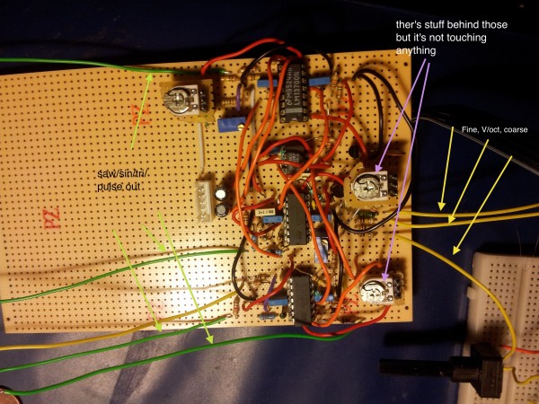
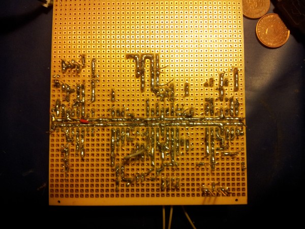
here is pictures of the "beast" (i know that no outputs are wired it's just to show you the circuit) i green saw/tri/pulse/sine waves, yellow are "command" wires (V/oct, coarse, fine, and PW, as the linear/expo fm as no wire for the moment but the circuits are soldered and same for the sync)
also there is a LOT of jumpers as you can see (don't if it could be the cause of the problem?)
edit : when i touch any metal parts (as trim pots for exemple) i don't have either sound or buzz but when i don't touch anything i have a buzz and no sound comming from the ouputs BUT i saw that i had +5v voltage between the triangle out and the ground (but don't know if it's +5 vpp as i can't see it)
| Description: |
|
| Filesize: |
1.9 MB |
| Viewed: |
399 Time(s) |
| This image has been reduced to fit the page. Click on it to enlarge. |
|
| Description: |
|
| Filesize: |
3.37 MB |
| Viewed: |
284 Time(s) |
| This image has been reduced to fit the page. Click on it to enlarge. |
|
|
|
|
Back to top
|
|
|
Janvier
Joined: Aug 12, 2014
Posts: 13
Location: Montréal
|
| Posted: Mon Dec 15, 2014 1:47 pm Post subject:
|
|
|
Can you take your multimeter and probe your GND. I mean... put one probe on a one GND path, and the other on another GND path (try one which is not to close to your first GND.
Do you measure a small mV value or it says 0V ?? |
|
|
Back to top
|
|
|
space_zulu
Joined: Dec 15, 2014
Posts: 13
Location: france
|
| Posted: Mon Dec 15, 2014 1:59 pm Post subject:
|
|
|
| yup, ok i just did it, the DVM calibrated on 200mV (the smallest i can get) and get most of the places 0,1mV but if the probe move (because i don't have proper test points) i sometimes get 1 to 3,5mV for less than a sec (may be a bug i don't know) could it be this ? |
|
|
Back to top
|
|
|
Janvier
Joined: Aug 12, 2014
Posts: 13
Location: Montréal
|
| Posted: Mon Dec 15, 2014 2:03 pm Post subject:
|
|
|
Hard to tell, a scope could help to see if you have weird noise on your ground !
At first it seems to be good !
Hum, what is your power supply ?? If you experience this with another design, then maybe your power supply is the problem. Is it possible for you to swap your circuit on another supply ? |
|
|
Back to top
|
|
|
space_zulu
Joined: Dec 15, 2014
Posts: 13
Location: france
|
| Posted: Mon Dec 15, 2014 2:11 pm Post subject:
|
|
|
well it's a wall wart that goes thru this schematic to deliver +12/0/-12v http://www.musicfromouterspace.com/forums.html?MAINTAB=SYNTHDIY&PROJARG=WALLWARTSUPPLY/WALLWARTSUPPLY.php&VPW=1252&VPH=500
i don't have a perfect +12/-12 but more -11,85V and +12,15V but i don't think that 15mv would do the difference in this case
unfortunatly i don't have another one to test if it is the cause of my issues :/
but i know that one day i forgot to remove 2 resistor that where laying on my desk and that i powerd my PSU just above it, it shorted it and an small electric arc pop appeared i turned it down and test it after but everything seemed (and still seems) ok. (i woulnd'nt be surprise if this could be the cause) |
|
|
Back to top
|
|
|
wackelpeter
Joined: May 05, 2013
Posts: 461
Location: germany
Audio files: 10
|
| Posted: Mon Dec 15, 2014 3:28 pm Post subject:
|
|
|
would suggest to check your solder Points again...
some look like there's a bad Connection and some Points on the pic look like shorts cuts between traces/Points...
next time better use stripboards much more better to solder as perfboard... i've build now around 40 modules on stripboard... the only bad Thing is that i sometimes Forget to drill/cut some traces...
instead of a tempco i use 2k2 NTC with an 3K9 or so resistor parallel it's not exactly the same compensation as with tempco but Close... i didn't noticed any drift by now, but it wasn't that hot when i finished my 555VCO's... we will see next summer if it really works under harder conditions...
_________________
https://soundcloud.com/bastian-j |
|
|
Back to top
|
|
|
space_zulu
Joined: Dec 15, 2014
Posts: 13
Location: france
|
| Posted: Mon Dec 15, 2014 3:40 pm Post subject:
|
|
|
| i think i'll do it tonight, i really want to get this thing finished quikly, for testing the connections in a more effective way what would you advise me ? i checked it with my dvm in the "diode mode" (don't how it's called^^') and everything looked ok except that between 2 "strip" it doesn't always says that there's no connection but it doesn't says that there is either, it just giving me odd numbers between 0 and 1999 that i don't understand... |
|
|
Back to top
|
|
|
space_zulu
Joined: Dec 15, 2014
Posts: 13
Location: france
|
| Posted: Tue Dec 16, 2014 2:02 pm Post subject:
|
|
|
hi again everyone,
today i went to my ex college, to use a scope, a descent volt/ampermeter and lab power supply (and got same results so my psu is out of the game for this ^^).
so the results are the following, everything that should be connected to the power supply are well connected (+v/-V/ground) the first op amps from IC3 and the expo converter works well (but i read -12v at the Q3 collector's) but when i test the loop TLC555 oscillator output, IC2a, and IC3c for charging and discharging C4, there a problem. i don't have any oscilation.
i tought i might be IC3 because it heated up but i works well, same for the 13700, so it might come from the 555 but can't figure from where... i see no shorts (even with a magnifying glass), everything is well connected, continuity is ok. so maybe the component is broken but i just bought it and it was used in this schematic only. if anyone as ideas it would be welcome again  i'll try some other things and i'll let you know the new stuff ! i'll try some other things and i'll let you know the new stuff !
(would it be possible to use a TS555 or a classic NE555 instead just to check ? or will the current consumption would be too important ?) |
|
|
Back to top
|
|
|
|

 Forum index » DIY Hardware and Software » Thomas Henry designs
