| Author |
Message |
Fenris

Joined: Jul 30, 2008
Posts: 145
Location: Horbury. UK
Audio files: 1
|
|
|
Back to top
|
|
 |
Fenris
Joined: Jul 30, 2008
Posts: 145
Location: Horbury. UK
Audio files: 1
|
 Posted: Fri Sep 25, 2015 1:24 am Post subject: Posted: Fri Sep 25, 2015 1:24 am Post subject:
|
  |
|
Hello there
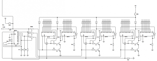
I've been beavering away with the 'design' of this sequencer and have now come up with a 3X16 design. I know I must be mental!
The block switcher (left hand side of image) I saw on a post by KRS1972. This can be set to run the 1st and 2nd pairs of 4017s for a total of 32 steps. Or for all 3 pairs to run for a total of 48 steps. At the moment I have the control logic done (took me ages to get it working due to clinical stupidity)
Of note if anyone tries this pin 9 on each second 4017 needs a diode going to the diode of the reset line to prevent power being pumped into pin 9.
Things to ponder: Each pair could have independent step range control. Also each pair could be switched to run in sync rather than in sequence.
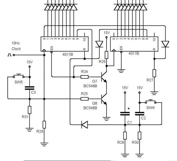
Also for reference is an image of a 16 step circuit. It seems newcomers get hung up on trying to go from 8/10 to a 16 step 4017. I remember going slightly nuts myself, many moons ago, trying to expand a circuit to some stupid size for a knight rider light effect. IIRC it needed 6 4017s. 3 to run up and 3 to run down, the outputs were paired using diodes. The logic control for this was four diode AND gates.
The other logic controls often seen to cascade multiple 4017s uses a, for example, CD4081 quad AND gate IC. One gate used for every additional 4017.
On this set of designs I use a transistor AND gate. Why? well it's easier to fit in the circuit 'real'. A CD4081 would be a waste for just a single pair and routing a PCB with more pairs I fear would get complicated. 
The diode AND gate is also small and easy to fit in, BUT, it makes my head hurt. Looking at the schematic for it, and even though I know it works, it makes my head hurt because it just looks 'wrong' in a counter intuitive way. 
Transistor AND gates are easier to understand and don't make my head hurt and they too work. 
4017 ICs, when turned on, can start at any where in the sequence because as the power levels up the 'noise' it makes causes the count to advance. So observe the capacitor resistor power on reset combo. a 10uF electrolytic and a 33/47K resistor holds the reset HIGH for around 1/2 a second which is long enough for the power fluctuations to pass. The reset then goes low and the count begins at the clock signal.
Note I have note shown decoupling caps. One, ceramic/poly, for each IC across the supply lines, close to the IC, keeps things clean of electrical noise that could 'clock' the 4017.
Fen
| Description: |
| Runs 32 or 48 steps as is |
|
| Filesize: |
19.01 KB |
| Viewed: |
586 Time(s) |
| This image has been reduced to fit the page. Click on it to enlarge. |
|
| Description: |
|
| Filesize: |
23.6 KB |
| Viewed: |
591 Time(s) |
| This image has been reduced to fit the page. Click on it to enlarge. |
|
_________________
Windows OS Sir?
No thanks. I'd rather shove wasps up my ass |
|
|
Back to top
|
|
|
Fenris
Joined: Jul 30, 2008
Posts: 145
Location: Horbury. UK
Audio files: 1
|
|
|
Back to top
|
|
|
PHOBoS

Joined: Jan 14, 2010
Posts: 5603
Location: Moon Base
Audio files: 705
|
| Posted: Sun Sep 27, 2015 5:23 am Post subject:
|
|
|
| Quote: | | Also as I've read about them, specifically the clone circuits, I see some have trigger and accent inputs. Although in certain cases I see these have been joined together I think I understand that the accent could be connected to a CV output as well as the trigger line just being fitted to the trigger. Is this correct? |
I've only build the cowbell and the accent is just another trigger input.
I'd personally use AND gates instead of the 4066 since you're working with digital signals only.
| Quote: | | Why didn't the chips designers have the outputs in sequential order? |
yeah what's up with that, it's something that has annoyed me with a bunch of chips, it probably has something to do with the manufactoring process I guess.
Have you tested the circuit on breadboard ? I have had some troubles with the 4017 not working as I expected before.

_________________
"My perf, it's full of holes!"
http://phobos.000space.com/
SoundCloud BandCamp MixCloud Stickney Synthyards Captain Collider Twitch YouTube |
|
|
Back to top
|
|
|
Fenris
Joined: Jul 30, 2008
Posts: 145
Location: Horbury. UK
Audio files: 1
|
| Posted: Sun Sep 27, 2015 10:03 am Post subject:
|
|
|
Hi PHOBos 
Apparently you can never have enough cowbells!
Curious about the accent. I'd seen in the posts by -minus- that although there are both trigger and accent inputs they had ended up either tying one high leaving only one line as the trigger or both had been tied together and used as the trigger.
Good call on AND gates. I've drawn and run that in 'sim' so that'll be the first of many changes I guess 
I've breadboarded 4017 circuits, and others, lots of times and other than 'user' errors I've not had any issue so far. The best user error ever was when I had just bought my first breadboard.
It was 3 boards held in a blue base. Running along the top edge of the boards was a power rail board two holes wide by enough holes to match the 3 boards it was attached to. My first setup was a voice chopper.
I built the preamp on the first board, the chopper on the second and the amplifier on the third. as each section was built I diligently fitted the +ve and -ve leads. I then spent 2 hours stripping it down and wondering why I was getting no chopped voice effect but could here local radio through the amplifier.
Eventually I noticed that the red and black strips on the power strip were different in what turned out to be ...... a quite important way 
The red line was one continuous line down the length of the strip. The black had two breaks in it's length. The black lines were the same length as each breadboard width...... I'll leave you to work out what that meant 
As regards breadboarding I have been warned that the boards themselves can have capacitive effects on circuits especially if running at higher frequencies.
Soooooo I only need to worry about a trigger circuit per 'drum' circuit.
Fen
_________________
Windows OS Sir?
No thanks. I'd rather shove wasps up my ass |
|
|
Back to top
|
|
|
Fenris
Joined: Jul 30, 2008
Posts: 145
Location: Horbury. UK
Audio files: 1
|
|
|
Back to top
|
|
|
elmegil

Joined: Mar 20, 2012
Posts: 2177
Location: Chicago
Audio files: 16
|
| Posted: Mon Sep 28, 2015 3:15 pm Post subject:
|
|
|
Time is short and I need to go back and re-read everything, but as for 808 voice circuits and trigger/accent inputs, it's usually easiest to just tie them together for simple stuff.
Note that if you want to feed CV to the accent, it expects a minimum of 4V and typical max of 14V so you might want to feed whatever CV in (assuming 0V -> whatever) to an offset of 4 or 5V to get it to behave as you'd like. |
|
|
Back to top
|
|
|
Fenris
Joined: Jul 30, 2008
Posts: 145
Location: Horbury. UK
Audio files: 1
|
Posted: Tue Sep 29, 2015 2:15 pm Post subject:
Subject description: The madness continues! |
|
|
Hello there
Thanks for the heads up elmegil. I've tweaked the CV pots with a change in resistor value on the wiper and the addition of a resistor ground side. Theoretically the values changed/added give me a 4.2V to 14.5V range.
I'll have a play on a breadboard at some point and see what transpires. That said I've doodled the schematic a bit more adding the CV out circuit and the trigger circuit. So the first irritant occurs..........
The CV out is a dual rail affair......... everything else is single rail. My understanding of op-amp design breaks down here in as much as I would like to change the CV circuit, circled in red, from dual rail to single rail can any kind soul help please? It's not for want of trying on my part but as much as I have read googled etc etc I lack the wit to do it 
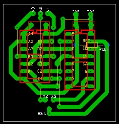
Also drawn up is the PCB for the sequence switcher. A 4017 and a 4081 plus one resistor on board.
here's the pics!
Fen
| Description: |
|
| Filesize: |
75.7 KB |
| Viewed: |
26638 Time(s) |
|
| Description: |
| schematic only one bank of outputs shown. |
|

Download |
| Filename: |
Circuit_Wizard_-_sequencer_switch_good3.pdf |
| Filesize: |
104.87 KB |
| Downloaded: |
539 Time(s) |
_________________
Windows OS Sir?
No thanks. I'd rather shove wasps up my ass |
|
|
Back to top
|
|
|
Fenris
Joined: Jul 30, 2008
Posts: 145
Location: Horbury. UK
Audio files: 1
|
| Posted: Sat Oct 03, 2015 12:00 am Post subject:
|
|
|
Hello there
Not much to show at the moment. Sorted out the dual rail to single rail CV side of things. Then refined it some more, thanks to input from PHOBos, CHEERS!
EDIT: I just realised I am an idiot of the first order.... the trigger circuit is also dual rail so I may as well have the CV as dual rail and have all the triggers and CV paired on one board powered by dual supply DOH! The CV still benefits from Master PHBos's input though
So at the moment I have a single PCB (16step) designed to build up to 3 banks (in theory more). Now my next technical question is.............
If I'm using 12V - 15V Dual rail supply. Obviously the sequencer will sit at +VE and GND whilst the drum circuits are dual rail. What can I have in terms of number of outputs from one sequencer module.
That is, currently I have one CV out and one trigger, this would go to one drum circuit. How many more CV out and trigger pairs could I reasonably add to one sequencer module?
Fen (rapidly going maaaaaaad!)
_________________
Windows OS Sir?
No thanks. I'd rather shove wasps up my ass |
|
|
Back to top
|
|
|
Fenris
Joined: Jul 30, 2008
Posts: 145
Location: Horbury. UK
Audio files: 1
|
|
|
Back to top
|
|
|
PHOBoS
Joined: Jan 14, 2010
Posts: 5603
Location: Moon Base
Audio files: 705
|
|
|
Back to top
|
|
|
Fenris
Joined: Jul 30, 2008
Posts: 145
Location: Horbury. UK
Audio files: 1
|
| Posted: Sat Oct 03, 2015 9:23 am Post subject:
|
|
|
Hello there
Cheers PHOBos. I knew I'd seen it mentioned! A search also brought it up as a standard issue it seems. I'm trying to recall if I ever had an issue with LED sequencers but I'm pretty sure I had no issue.
Though that begs the question does the differing end use have an effect? Can't see it but who knows?
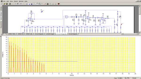
I know the software I use is only indicative not accurate. I've done an overlay of the CV steps on the CV/trigger spikes the first (extra spike) occurs on the CV rising edge the last spike occurs on the CV falling edge and the intermediate spikes are at the end of each step. Thats in the first 4017.
The second 4017 spikes all sit center of each CV step which seems more normal. I tried using a transistor on the clock line and this fixed the first 4017 group but then the second 4017 group drifted late and the extra pulse occurred in that group instead
I really will have to bread board the basic 16 step sequencer and see what occurs. Duly noted the links provided thank you.
What are your thoughts on the loading on the outputs in terms of how far can you go? So how many drum type circuits could I possibly drive maximum?
Piezo...... Piezo, Piezo, Piezo!!!! Thanks for the zzzzzz's I can talk proper again innit!
Fen
_________________
Windows OS Sir?
No thanks. I'd rather shove wasps up my ass |
|
|
Back to top
|
|
|
Fenris
Joined: Jul 30, 2008
Posts: 145
Location: Horbury. UK
Audio files: 1
|
| Posted: Sat Oct 03, 2015 3:03 pm Post subject:
|
|
|
I'm worried..................
Shhhhhhhhhhh. I think my laptop is, or at least the software is sentient.
After hours of fiddling around with pulse delay sub-circuits, components etc etc. All to no avail in getting rid of the extra pulse. It is now only doing it on the initial startup (in sim) all the following iterations have only 8 pulses per 4017......... I think the software worked out what I wanted and did it...........
That said I am on new meds for chronic migraine but I'm damn sure it was having the extra spike on all previous runs. Honest o_O
Fen (Terminally Bemused)
_________________
Windows OS Sir?
No thanks. I'd rather shove wasps up my ass |
|
|
Back to top
|
|
|
PHOBoS
Joined: Jan 14, 2010
Posts: 5603
Location: Moon Base
Audio files: 705
|
| Posted: Sat Oct 03, 2015 5:14 pm Post subject:
|
|
|
| Fenris wrote: | | What are your thoughts on the loading on the outputs in terms of how far can you go? So how many drum type circuits could I possibly drive maximum? |
depends on what you are driving it with and the input impedance of the 808 circuits.
with the transistors on the outputs you'll probably can drive a lot of them, straight from CMOS not so many,
better to add some buffers to that anyway. (voltage follower is also very useful for that)
and here's another 16 step that might save you some trouble:
http://electro-music.com/forum/post-404558.html#404558
of course you would have to start over with the PCB design.
_________________
"My perf, it's full of holes!"
http://phobos.000space.com/
SoundCloud BandCamp MixCloud Stickney Synthyards Captain Collider Twitch YouTube |
|
|
Back to top
|
|
|
Fenris
Joined: Jul 30, 2008
Posts: 145
Location: Horbury. UK
Audio files: 1
|
| Posted: Sun Oct 04, 2015 1:54 am Post subject:
|
|
|
LOL! This is getting out of hand I fear!
OK so I need to work backwards. what drums do I want (all of them)
Cymbal, Hi-hat open, Hi-hat closed, Kick drum, Snare, Tom (more than one?)
I think patchable to chop and change. I can start small build up.
SO the sequencer. Will need a gate and trigger per drum unit added.
Voltage followers Do I need a voltage follower per output per drum unit?
or diode the outputs to a follower per drum unit.
other than that. the thought occurs.... I have a bucket load of 4017s. Make one 16 step sequencer per drum running from a common clock or pairs of drums on one stepper to spread the load............
lawks I feel like I'm right back at the beginning......aged 14 armed with a 36Watt iron (dad gave me) wondering why nothing works
fen
_________________
Windows OS Sir?
No thanks. I'd rather shove wasps up my ass |
|
|
Back to top
|
|
|
PHOBoS
Joined: Jan 14, 2010
Posts: 5603
Location: Moon Base
Audio files: 705
|
| Posted: Sun Oct 04, 2015 3:27 am Post subject:
|
|
|
| Fenris wrote: | | Voltage followers Do I need a voltage follower per output per drum unit? |
That would be 1 for every sequencer output with which you could drive more than 1 drum unit (of course if you connect
more than 1 they do the same thing). But I think for drums a transister output might actually be easier and work great.
I often prefer voltage followers because they can provide both a positive and negative voltage (negative could also be 0V)
while transistors (when used as a switch) can only provide one of the two. They are most useful for analog though and since
your trigger outputs are just on/off and you only need a positive voltage transistors would probably be the prefered choice.
They can also drive much more than a standard opamp. However keep in mind that transistors don't have a short circuit
protection so I'd put a small resistor in series with the ouput.
| Quote: | | Make one 16 step sequencer per drum running from a common clock or pairs of drums on one stepper to spread the load............ |
One per drum, this makes it possible to clock from different sources (maybe something like a divider, or swing generator)
and you can get much more interesting rhythms by using a different number of steps for each sequencer (I like primes).
So just start with 1 16 step sequencer and than you can build more of them later on, you might also come up with some
new ideas after you've made the first one.
btw I've had it happen more than once where I was almost done with the design and than came up with a different
way to do it and had to start over from scratch.
Here's some music to listen to while you think about it:
https://www.youtube.com/watch?v=conwt8Dy27Y&list=PL359FFEB4FDC11841 
_________________
"My perf, it's full of holes!"
http://phobos.000space.com/
SoundCloud BandCamp MixCloud Stickney Synthyards Captain Collider Twitch YouTube |
|
|
Back to top
|
|
|
Fenris
Joined: Jul 30, 2008
Posts: 145
Location: Horbury. UK
Audio files: 1
|
|
|
Back to top
|
|
|
Fenris
Joined: Jul 30, 2008
Posts: 145
Location: Horbury. UK
Audio files: 1
|
Posted: Fri Oct 16, 2015 12:39 pm Post subject:
Subject description: Filling an empty head! |
|
|
hello there
well it's day four and no migraine or even a hint of one......shhhhh!
with this clear headedness I can at last string coherent thoughts together for long periods of time. We're talking DAYS!
Anyway here goes. I've been 'designing', in the loosest sense of the word my modular drum sequencer. Despite the corporeal build delay I will be able to test the cmos core of the theoretical circuit I've cobbled together from disparate parts gleaned from posts all over the web.
But mainly here, MFOS, and a randomly stumbled upon PE sequencer PDF scanned document.
So the core circuit is a pair of CD4017, One CD4081 and a CD4001. With these chips I can run a 1 x 16 or, at the flick of a switch, 2 x 8 sequencers.
Primarily the above is taken from the Practical Electronics March 1979 Sequencer project. Although it has to be said, and it looks like some scribbles on the scans indicate, there is an error in the latch logic of the schematic that bugger up an otherwise neat idea. I don't know if the PCB patterns have the same error but I'm rolling my own anyway......well I will be and my output interface is totally different anyway.
That said I worked out how to get the latch logic sorted so that you could actually switch between 1 x 16 or 2 x 8. in 2 x 8 mode each 4017 can have it's own clock drive.
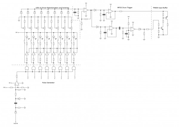
After that I pulled all the disparate parts of the output interface together. To match one CD4017 I need 2 CD4081 IC's to form the pulse OUT in conjunction with a gate to trigger circuit.
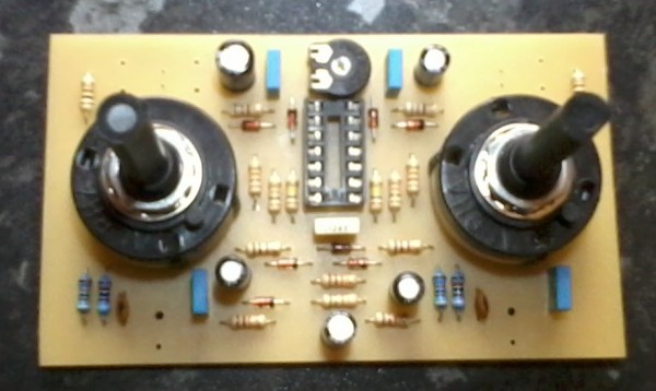
To each OUT of the 4081 a switch and pot for CV. Also here a tap out for an LED on each OUT for indication when sequencing. On the OUT of each pot a signal diode. These are then summed into what is the MFOS drum trigger circuit.
On Rays site this is shown with a piezo on the input. The circuit is divided into two parts. The first half outputs a CV output. For synth drums I understand this is termed velocity. The harder the piezo is struck the greater the initial voltage level the softer the lower the level. This effects the apparent sound of the synth drum. The other half of the circuit provides the trigger, a 5V pulse commonly, though some units vary in requirement.
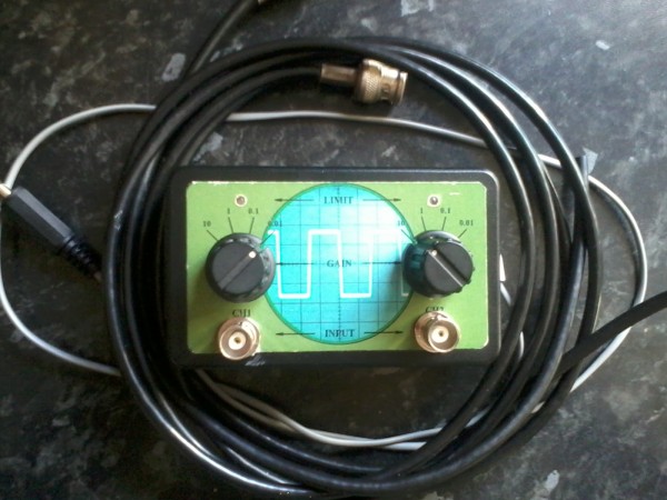
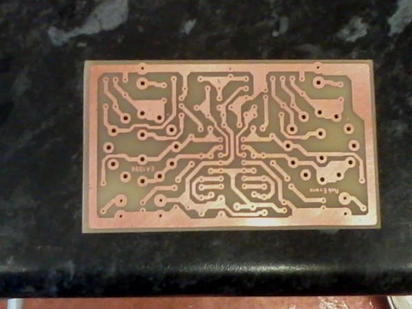
Thats it up to that point. There is some finessing to do and some ideas bubbling under. Today I also etched and drilled my first PCB in ages, for the sound card oscilloscope. good fun!
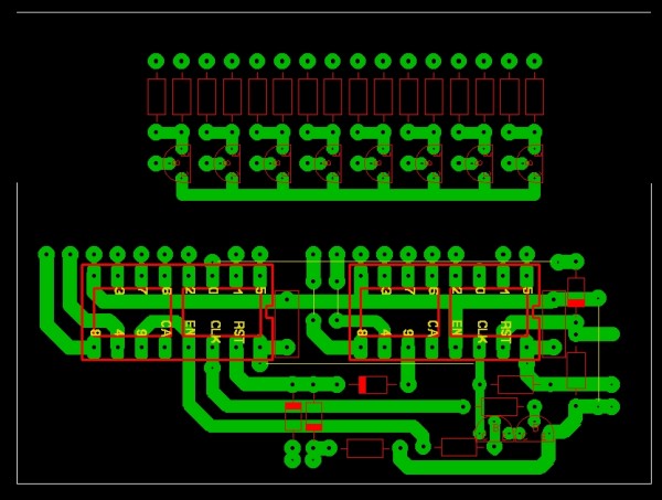
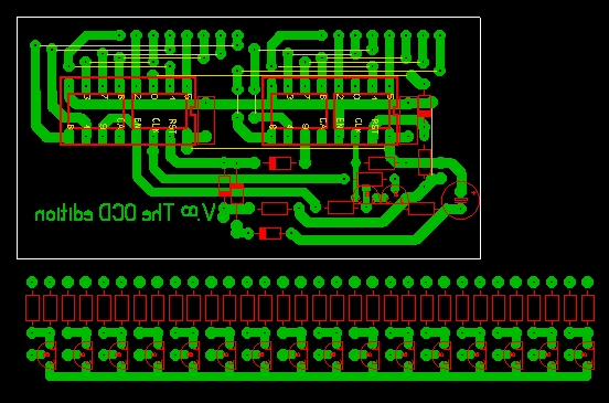
Here's a pic of the output circuit to give you the idea and a pic of the PCB I've just done. Toner transfer method FTW!
Fen
| Description: |
|
| Filesize: |
405.57 KB |
| Viewed: |
504 Time(s) |
| This image has been reduced to fit the page. Click on it to enlarge. |
|
| Description: |
|
| Filesize: |
409.37 KB |
| Viewed: |
420 Time(s) |
| This image has been reduced to fit the page. Click on it to enlarge. |
|
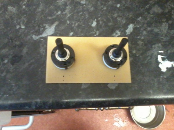
| Description: |
| I had to cut the eyes off the pins on both! |
|
| Filesize: |
520.54 KB |
| Viewed: |
401 Time(s) |
| This image has been reduced to fit the page. Click on it to enlarge. |
|
_________________
Windows OS Sir?
No thanks. I'd rather shove wasps up my ass |
|
|
Back to top
|
|
|
Fenris
Joined: Jul 30, 2008
Posts: 145
Location: Horbury. UK
Audio files: 1
|
Posted: Sat Oct 17, 2015 7:54 am Post subject:
The PE Sequencer Core Corrections
Subject description: Practical Electronics Sequencer March 1979 |
|
|
Hello there
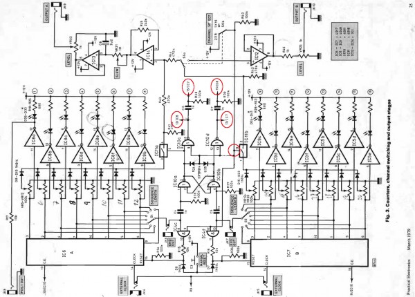
As mentioned previously. The core of my proposed sequencer has come from the PE sequencer. Also as mentioned I had to correct the schematic for it to work.
Now the correction was only partial it turns out. Everything still works but I spotted a further error in the same area. Its not major but having had a brief look I do believe the error may have made it onto the PCB patterns in the PDF scan.
At this juncture I will say I am quite prepared to be called out if I have got any part of this wrong. I have only run the corrected circuit in a simulator both as it was and now how it is. One works..... The other doesn't.
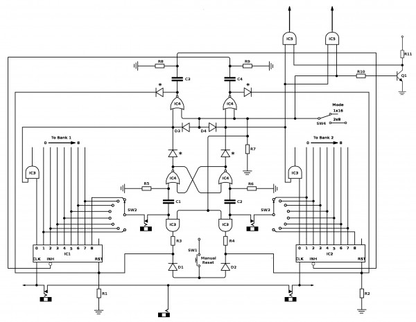
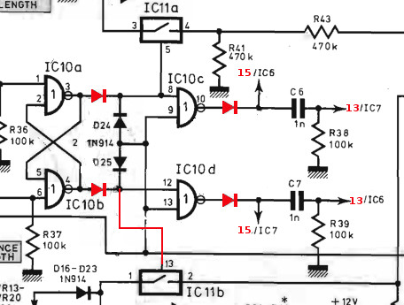
So basically if you look at the main picture. You can see that there are a few red circles on the page. This is me denoting errors. The primary error is the CD4016. It is erroneously connected to the mode switch line. In this state it fails to function in 1 x 16 mode as it never gets a logic 1 EVER.
What is supposed to happen is when IC6 is running its CD4016 Switch closes so its summed outputs are passed out. When IC6 resets at the end of its run, its CD4016 opens and the sequence continues on IC7 whos CD4016 switch has also closed so the summed outputs can be passed out.
The cycle loops round continuously of course. The only time IC7s CD4016 switch will close is when you switch modes to 2 x 8. In the mode both CD4016 switches close and both 4017 ICs run (They can be clocked independently).
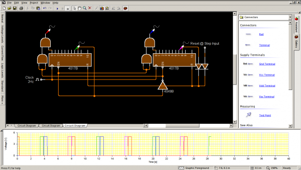
You can see in the smaller image a red line now goes from the effected CD4016 to the Steering diode above it. This is the only connection between the switch and the diode.
Initially I had removed the mode line between the IC10d pin 13 and IC4d pin 12. electing to hold pin 12 and its fellow pin 9 high to maintain reset functionality in both modes. So at that point I now had both modes working and reset operated in both (initially it didn't after the mode line removal)
Things took a slight down turn when I realised that I could reinstate the mode line. But then the reset went wyrd (in an old english sort of way) Which brings me to the other red circles. These are the logic controls to the enables and reset pins of both 4017 ICs. To get these to work again basically the lines marked to go to pins 15 and 13 circled in red should be transposed to 13 and 15 (same ICs just change the pin destination).
RED DIODES: Hmmm. OK this is me. In the sim software without these even with the faults fixed things don't work properly. All the positive voltage seems to shoot into the outputs of the NAND gates stopping the 4016 switches closing and stopping the change over latch working. In real life This probably wouldn't happen. but to get things to work in sim and prove the faults fixed I had to drop them in. Other than that I'm wary of throwing INPUT voltages (12V in this case) into OUTPUT terminations. If any one has wise words as regards this please say!
Then everything works lovely.
Note I am note sure on copy write so I am only posting the page of the schematic for reference in case anyone out there finds the PDF scan for themselves and wishes to give it a bash. Hopefully they see this before trying it out though :/
Fen
.
| Description: |
| This'll do it. Go to the top of the class and sharpen all the rubbers! |
|
| Filesize: |
40.62 KB |
| Viewed: |
25846 Time(s) |
|
| Description: |
| Incorrect! See me for detention after class! |
|
| Filesize: |
310.34 KB |
| Viewed: |
427 Time(s) |
| This image has been reduced to fit the page. Click on it to enlarge. |
|
_________________
Windows OS Sir?
No thanks. I'd rather shove wasps up my ass |
|
|
Back to top
|
|
|
Fenris
Joined: Jul 30, 2008
Posts: 145
Location: Horbury. UK
Audio files: 1
|
|
|
Back to top
|
|
|
Fenris
Joined: Jul 30, 2008
Posts: 145
Location: Horbury. UK
Audio files: 1
|
|
|
Back to top
|
|
|
PHOBoS
Joined: Jan 14, 2010
Posts: 5603
Location: Moon Base
Audio files: 705
|
|
|
Back to top
|
|
|
Fenris
Joined: Jul 30, 2008
Posts: 145
Location: Horbury. UK
Audio files: 1
|
|
|
Back to top
|
|
|
Fenris
Joined: Jul 30, 2008
Posts: 145
Location: Horbury. UK
Audio files: 1
|
| Posted: Fri Oct 23, 2015 2:36 am Post subject:
|
|
|
Hello Chaps
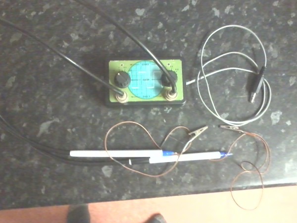
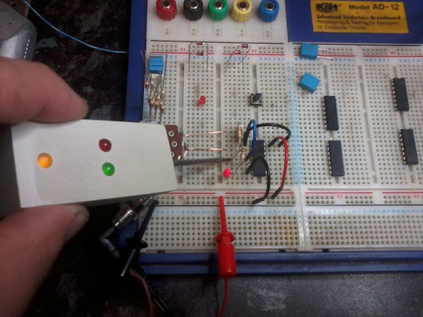
Well I think the game plan is forming a more coherent path. Last night I finished boxing a logic probe I made a few years ago. This will be good for testing logic states around the sequencer core of course.
The on to the plan.
Bread boarding the sequencer core (yay) hopefully today. If not at least clearing the board and plugging the chips in.
Things in the pipe line - Drawn up a PCB of the MFOS drum trigger. This will be useful to test the 808 circuits as they are done.
Ripped open a 12V 1A DC wall wart for its transformer. This will become the 12V AC supply for the 12V bipolar supply ala MFOS stylee. PLEASE DO NOT DO THIS IF YOU AREN'T MAINS CONFIDENT! I've had a few years under my belt and have never had an accident and despite this have never become complacent in the presence of mains (240V UK) voltage.
My intent is to draw up a bespoke PCB which will have the transformer on it with the requisite circuit to create the bipolar output. This will be housed in a plastic enclosure when finished. I realised late in the day I would need a Bi supply and I have the parts to do this.
Also to warm up my soldering skills, now my head is free of the migraine (shhh), I'm making a surf synth effect circuit for the wife to relax to. Her health is not robust and anything that helps has got to be a good thing.
more later
Fen
_________________
Windows OS Sir?
No thanks. I'd rather shove wasps up my ass |
|
|
Back to top
|
|
|
Fenris
Joined: Jul 30, 2008
Posts: 145
Location: Horbury. UK
Audio files: 1
|
|
|
Back to top
|
|
|
|

 Forum index » DIY Hardware and Software » Musical Interfaces