| Author |
Message |
tokyomatik

Joined: Jan 20, 2011
Posts: 171
Location: berlin
Audio files: 6
|
 Posted: Mon Apr 20, 2015 1:06 pm Post subject: Posted: Mon Apr 20, 2015 1:06 pm Post subject:
|
  |
|
| richardc64 wrote: | | commathe wrote: | | I want to be passing tri/saw/sine signals without too much distortion and definitely not clipping so the diode/transistor method is out. |
I failed to mention that omitting the 2nd diode from the 2-diode VCA the circuit handles analog as well digital inputs. Replacing the transistor in the "1-transistor" VCA with a single supply opamp makes it even better, as it allows bigger input swings.
|
looks like richardc64 already answered about this matter.....
so now refering to the pcb from hexagon5un
is D2 the 2nd diode mentioned by richardc64?? |
|
|
Back to top
|
|
 |
hexagon5un
Joined: Apr 10, 2009
Posts: 38
Location: Munich, Germany
Audio files: 1
|
| Posted: Fri Apr 24, 2015 1:25 pm Post subject:
|
|
|
Heya! Sorry to come so late to the party here.
I actually had my old Lunetta modular in pieces in a box in the basement, and I found/pulled out the VCA circuit just now to see how it works with non-square waves. It's freaky!
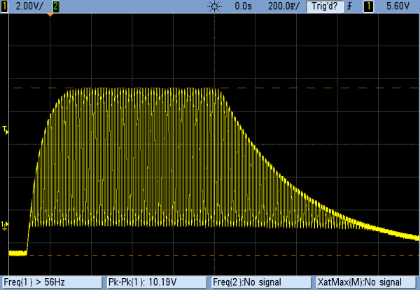
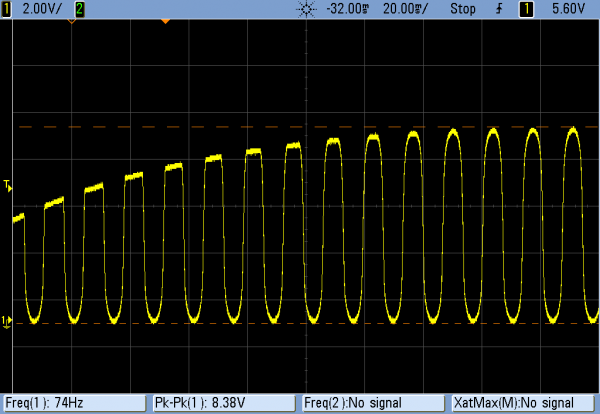
Input is a (slightly overdriven) sine wave at 73ish Hz.
I've attached scope shots at two resolutions: one is the overall envelope and the other is a zoom into the top of the wave.
The waveform is actually pretty clean during the sustain portion, but you can see the strange way it's clipped during the attack and release. Pretty neat.
I also recorded this just for fun. I'm not 100% sure that I'm not distorting it further in my laptop, but you get the idea. It's got this woooomp kind of noise at the beginning for slow attacks. (I play around with attack and release a bit.)
Anyway, that's the deal with the active version of the circuit and non-square waves. Works great, but idiosyncratically.
edit: Oh yeah. I built the circuit without the output capacitor because I was using it for control voltages as well as audio, which make the super-long envelopes that it can produce even more reasonable. If you etch/build my version of the board, look out for that and add one if you're only doing audio processing.
Who knows which version I posted? 
| Description: |
|
| Filesize: |
8.36 KB |
| Viewed: |
706 Time(s) |
| This image has been reduced to fit the page. Click on it to enlarge. |
|
| Description: |
|
| Filesize: |
9.52 KB |
| Viewed: |
667 Time(s) |
| This image has been reduced to fit the page. Click on it to enlarge. |
|
| Description: |
|

Download |
| Filename: |
single_sided_vca_demo.mp3 |
| Filesize: |
1.11 MB |
| Downloaded: |
974 Time(s) |
|
|
|
Back to top
|
|
|
tokyomatik
Joined: Jan 20, 2011
Posts: 171
Location: berlin
Audio files: 6
|
| Posted: Fri Apr 24, 2015 2:19 pm Post subject:
|
|
|
oh well
actually i posted here the version i etched (just a couple of msgs before) that is the same that u posted (9msgs before mine)
on the board i have in, out & cv
but in wich way u trigger the envelope??, than i thought that maybe you meant Gate...??
since this board looks a bit inspired by the schematics of richard64....
referring to the 2nd diode, is that D2 on your board?
thanks for jumping in and for sharing your pcb, saving us a lot of stress...
at least after that maybe i will have it more clear
 |
|
|
Back to top
|
|
|
hexagon5un
Joined: Apr 10, 2009
Posts: 38
Location: Munich, Germany
Audio files: 1
|
| Posted: Fri Apr 24, 2015 2:22 pm Post subject:
|
|
|
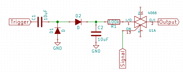
And then to answer a curiosity of mine about the two-diode VCA circuit.
I built it exactly as indicated (with a 10uF cap on the output) and then pulled out the last / output diode.
Somewhere in between, I switched to 5V supply, so the input is a 5V sine wave at ~75Hz.
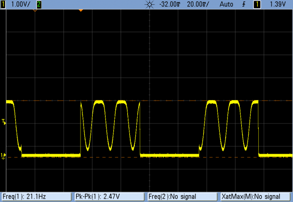
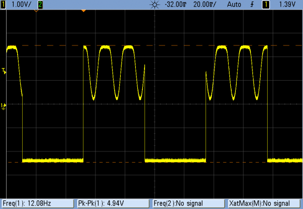
I did two experiements. First, I used a 5V square wave as the control voltage, and ran it with and without the output diode so you could see the effect at a constant level.
The only thing different is that the full swing of the control voltage (that shows up as negative through the cap) is supressed by the output diode. But I'd say that both work "fine" with analog signals, though the sinewave is visibly flattened at the top. (My guess, by the diode drop of the "input" diode.)
I guess you want the output diode in there, though, because there'll be a thump at the turn-on with a square wave control voltage, and it's going to be louder in the single diode version.
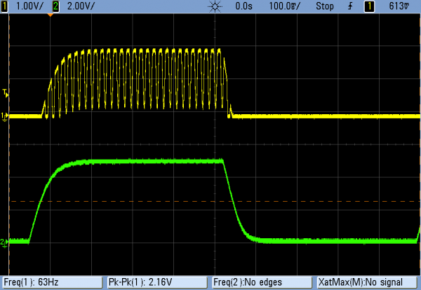
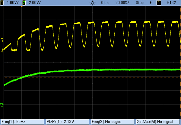
Then I tossed a 47uF cap on the control voltage to smooth it out, and hooked up the scope (in green) to the CV input. Not entirely surprisingly, the performance is a lot like the op-amp buffered version of the same thing in my last post.
So there you go. The buffers in the op-amp probably help a bunch to make the attack/release part perform more consistently, but otherwise don't seem to do much. OTOH, it's nice to have those long swooping envelopes.
The sine wave came through a bit less distorted in the op-amp version because it's being amplified before the diode, but it's really not that big of a deal.
| Description: |
RichardC64's two-diode VCA, but this time fed with sine-wave input.
The circled diode is the one removed in the square-wave-CV experiments. |
|
| Filesize: |
2.45 KB |
| Viewed: |
32897 Time(s) |
|
| Description: |
| Two-diode VCA as per Richardc64's circuit. 10uF cap on output. |
|
| Filesize: |
8.07 KB |
| Viewed: |
708 Time(s) |
| This image has been reduced to fit the page. Click on it to enlarge. |
|
| Description: |
| Same, but omitting output diode. |
|
| Filesize: |
8.32 KB |
| Viewed: |
697 Time(s) |
| This image has been reduced to fit the page. Click on it to enlarge. |
|
| Description: |
| Two diode VCA, both diodes, driven by a more analog control voltage (in green). Both diodes. |
|
| Filesize: |
9.27 KB |
| Viewed: |
665 Time(s) |
| This image has been reduced to fit the page. Click on it to enlarge. |
|
| Description: |
| Two-diode VCA, analog CV, analog input. Detail of envelope ramp and (slightly distorted) sine wave input. |
|
| Filesize: |
9.82 KB |
| Viewed: |
701 Time(s) |
| This image has been reduced to fit the page. Click on it to enlarge. |
|
Last edited by hexagon5un on Fri Apr 24, 2015 2:38 pm; edited 2 times in total |
|
|
Back to top
|
|
|
hexagon5un
Joined: Apr 10, 2009
Posts: 38
Location: Munich, Germany
Audio files: 1
|
| Posted: Fri Apr 24, 2015 2:31 pm Post subject:
|
|
|
| tokyomatik wrote: | oh well
actually i posted here the version i etched (just a couple of msgs before) that is the same that u posted (9msgs before mine)
on the board i have in, out & cv
but in wich way u trigger the envelope??, than i thought that maybe you meant Gate...?? |
It's no big deal to just solder on an output capacitor if you want one. Just put one leg in the circuit board's hole, and solder the other to your output wire.
And yeah, I guess I meant "gate". There's an audio input and then there's the control voltage / gate input.
If you send too short a CV pulse in, and have the attack set very long, nothing happens. So in that sense, you surely want a "gate" rather than a "trigger". |
|
|
Back to top
|
|
|
tokyomatik
Joined: Jan 20, 2011
Posts: 171
Location: berlin
Audio files: 6
|
| Posted: Tue Jun 02, 2015 7:56 pm Post subject:
|
|
|
| hexagon5un wrote: | | tokyomatik wrote: | oh well
actually i posted here the version i etched (just a couple of msgs before) that is the same that u posted (9msgs before mine)
on the board i have in, out & cv
but in wich way u trigger the envelope??, than i thought that maybe you meant Gate...?? |
It's no big deal to just solder on an output capacitor if you want one. Just put one leg in the circuit board's hole, and solder the other to your output wire.
And yeah, I guess I meant "gate". There's an audio input and then there's the control voltage / gate input.
If you send too short a CV pulse in, and have the attack set very long, nothing happens. So in that sense, you surely want a "gate" rather than a "trigger". |
....So I actually build the pcb using your layout and all the parts/values suggested..... it works
sine waves are a bit distorted and there is a bit of volume drop
my idea was to use this circuit to make a small percussive envelope/vca
so honestly i dont need the attack pot, at least on the amplitude, or maybe i could reduce from 1M to 500k or less, to have a shorter attack
the circuit anyway it's so small that i could use 2 together with common gate input so that one is taking care of the vca and the other for a kind of "sweep" frequency
in case I wanna have more volume without adding distorsion(eventually less distorsion would be even better)...do u have any more suggestion?
and if I wanna remove the attack pot?
i'm powering everything with 12v wallwart....  |
|
|
Back to top
|
|
|
Steveg

Joined: Apr 23, 2015
Posts: 182
Location: Perth, Australia
|
| Posted: Wed Jun 03, 2015 1:02 am Post subject:
|
|
|
I haven't seen any mention of the simple one transistor VCA synaesthesia used in his gong drone http://electro-music.com/forum/topic-62791.html. I guess it is the same as the ones PHOBoS posted without the op-amp buffer.
Also the "diode vca and ar.jpg" circuit should be able to be used with any control voltage driving the lower LM358 you don't have to use the depicted AR generator. |
|
|
Back to top
|
|
|
Steveg
Joined: Apr 23, 2015
Posts: 182
Location: Perth, Australia
|
|
|
Back to top
|
|
|
okelk
Joined: May 08, 2014
Posts: 71
Location: Vienna
|
| Posted: Wed Jun 03, 2015 3:23 am Post subject:
|
|
|
thanks but...the link doesn't work.. |
|
|
Back to top
|
|
|
Steveg
Joined: Apr 23, 2015
Posts: 182
Location: Perth, Australia
|
| Posted: Wed Jun 03, 2015 3:28 am Post subject:
|
|
|
I think the site must have just gone down ... it worked ok 15 minutes ago and my bookmark is having the same problem.
[edit] It is working again. |
|
|
Back to top
|
|
|
richardc64

Joined: Jun 01, 2006
Posts: 679
Location: NYC
Audio files: 26
|
| Posted: Wed Jun 03, 2015 8:00 pm Post subject:
|
|
|
Let's not forget that the original inquiry was for a single-supply VCA. Many of the circuits that have been suggested will need modification to operate single-supply -- the more complex circuits needing more that just a pseudo ground of 1/2V+.
Let's also not forget where we are: The Lunetta sub-forum.
| mosc wrote: | | Lunettas are very simple, digital, noisy, quirky, and lots of fun. |
Low distortion need not be a major concern.
_________________
Revenge is a dish best served with a fork... to the eye |
|
|
Back to top
|
|
|
blue hell
Site Admin

Joined: Apr 03, 2004
Posts: 24085
Location: The Netherlands, Enschede
Audio files: 278
G2 patch files: 320
|
| Posted: Thu Jun 04, 2015 6:14 am Post subject:
|
|
|
Hey ... you quit smoking, great :-)

_________________
Jan
also .. could someone please turn down the thermostat a bit.
 |
|
|
Back to top
|
|
|
Steveg
Joined: Apr 23, 2015
Posts: 182
Location: Perth, Australia
|
|
|
Back to top
|
|
|
richardc64
Joined: Jun 01, 2006
Posts: 679
Location: NYC
Audio files: 26
|
| Posted: Thu Jun 04, 2015 9:27 am Post subject:
|
|
|
Original idea of Tom Servo.
| Blue Hell wrote: | Hey ... you quit smoking, great  |
Actually, I haven't. I just thought that since his passing Mr. Nimoy should be depicted without a cigarette.
I still endorse his quotation as my sig 
_________________
Revenge is a dish best served with a fork... to the eye |
|
|
Back to top
|
|
|
jurekprzezdziecki
Joined: Mar 22, 2016
Posts: 68
Location: warsaw
|
| Posted: Mon Sep 12, 2016 2:24 am Post subject:
|
|
|
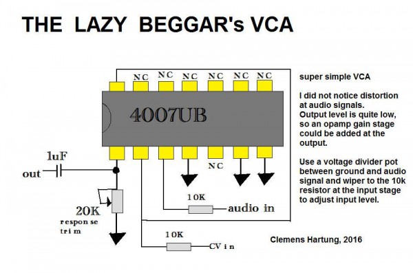
| commathe wrote: | Thanks again guys! It is time to get bread boarding and see what gets closest. Simulations of the MFOS one are looking ok. More distortion than I'd like but beggars can't be choosers!
EDIT: I just discovered this 4007 based VCA that I would have just glanced over if it wasn't for the fact that I have a note that the schematic as it is drawn here is WRONG. The body connections of the internal MOSFETs are tied to Vss and Vdd, meaning that this may actually work! |
so did you tested this 4007 circuit finally? is it well designed? |
|
|
Back to top
|
|
|
kybernetika
Joined: Mar 30, 2016
Posts: 6
Location: NL
|
|
|
Back to top
|
|
|
Hammer

Joined: Mar 13, 2018
Posts: 72
Location: Russia, Zhukovsky
Audio files: 23
|
| Posted: Tue Mar 13, 2018 11:30 pm Post subject:
|
|
|
Is it posible to make LPF with TDA7052A like this: http://electro-music.com/forum/topic-34891.html
It could be VCA + LPF just in one tiny chip.
Last edited by Hammer on Thu Mar 15, 2018 3:40 am; edited 1 time in total |
|
|
Back to top
|
|
|
Steveg
Joined: Apr 23, 2015
Posts: 182
Location: Perth, Australia
|
| Posted: Wed Mar 14, 2018 12:43 am Post subject:
|
|
|
Hi Hammer, I've just trawled through that thread but I can't see anything relating to a TDA7052. Mostly it is about sallen-key filters.
I have been trawling through a lot of posts recently and I'm sure I've seen something talking about using a low pass VCF as a VCA. The resting state of the filter is sub-sonic and you feed it an envelope that raises the cutoff frequency and as the signal moves higher on the attenuation slope more is passed. It would probably not work too well for mixed frequencies because the attenuation is frequency dependent.
Is that what you were thinking of? |
|
|
Back to top
|
|
|
Hammer
Joined: Mar 13, 2018
Posts: 72
Location: Russia, Zhukovsky
Audio files: 23
|
| Posted: Wed Mar 14, 2018 1:05 am Post subject:
|
|
|
Hello, Steveg!
I'm talking about circuit from first page of this topic (elektrouwe):
 |
|
|
Back to top
|
|
|
Steveg
Joined: Apr 23, 2015
Posts: 182
Location: Perth, Australia
|
| Posted: Wed Mar 14, 2018 3:07 am Post subject:
|
|
|
Without knowing much about the chip I thought at first it might be possible but the more I look at it the less certain I am. The differential outputs might be a problem. Electrouwe seems to only use one output so I guess it could be used as a voltage controlled attenuator. You would need two in a Sallen Key or State Variable filter.
The link you supplied is to a completely different thread which is why I was confused. |
|
|
Back to top
|
|
|
Hammer
Joined: Mar 13, 2018
Posts: 72
Location: Russia, Zhukovsky
Audio files: 23
|
| Posted: Wed Mar 14, 2018 3:32 am Post subject:
|
|
|
Steveg, thank you for reply! Today I will get this TDA chips, will see...
| Steveg wrote: | | Electrouwe seems to only use one output so I guess it could be used as a voltage controlled attenuator. |
And he doesn't use signal ground pin. But it's nessesary for me. |
|
|
Back to top
|
|
|
Harry
Joined: May 09, 2017
Posts: 20
Location: Texas
|
| Posted: Wed Mar 14, 2018 10:15 am Post subject:
|
|
|
| Steveg wrote: | I have been trawling through a lot of posts recently and I'm sure I've seen something talking about using a low pass VCF as a VCA. The resting state of the filter is sub-sonic and you feed it an envelope that raises the cutoff frequency and as the signal moves higher on the attenuation slope more is passed. It would probably not work too well for mixed frequencies because the attenuation is frequency dependent.
Is that what you were thinking of? |
Sounds like you're describing a (Buchla) Low Pass Gate. Can operate as a low-pass filter, vca or both simultaneously.
 |
|
|
Back to top
|
|
|
Hammer
Joined: Mar 13, 2018
Posts: 72
Location: Russia, Zhukovsky
Audio files: 23
|
| Posted: Thu Mar 15, 2018 2:02 am Post subject:
|
|
|
TDA 7052A sounds a lot better than all this single transistor and diode VCA!
But I can't eliminate distortions. And it works a little bit weird. I'm using Arduino with DDS output as source. TDA 7052 is not distort the signal if there are no any caps in input (even DDS cap), the same thing with simpliest 40106 oscillator. And I can't understand why.
In spite of this, it works very well with this 4069 LPF: http://aeeprojects.blogspot.ru/2011/09/filters-with-cd4069.html
What can I do with differential outputs? May be any audio transformer will be correct decision?
Last edited by Hammer on Thu Mar 15, 2018 2:34 am; edited 1 time in total |
|
|
Back to top
|
|
|
elektrouwe
Joined: May 27, 2012
Posts: 143
Location: Germany
|
| Posted: Thu Mar 15, 2018 2:34 am Post subject:
|
|
|
| Hammer wrote: | | TDA 7052 sounds a lot better than all this single transistor and diode VCA! |
that's why I suggested it
PS: please write TDA7052A, because when people read your post and buy a TDA7052 it will not work because this one has no DC gain control pin !
| Hammer wrote: |
But I can't eliminate distortions. |
TDA7052A has a gain of ~ 56x, which means Vin should be in the 100mV range, otherwise you need an input voltage divider. You MUST use an input coupling cap., because the chip generates an internal DC bias voltage.
| Hammer wrote: |
What can I do with differential outputs? |
unless you don't need diff. outputs, just use 1 of them. Inverting or noninverting is only important if you use the chip in a filter loop |
|
|
Back to top
|
|
|
Hammer
Joined: Mar 13, 2018
Posts: 72
Location: Russia, Zhukovsky
Audio files: 23
|
| Posted: Thu Mar 15, 2018 3:39 am Post subject:
|
|
|
| Yes, input cap. was too small, signal was too high! Thank you a lot, now it's working as it should. |
|
|
Back to top
|
|
|
|

 Forum index » DIY Hardware and Software » Lunettas - circuits inspired by Stanley Lunetta