| Author |
Message |
alanwilder81
Joined: Sep 03, 2016
Posts: 310
Location: italy
|
 Posted: Thu Dec 01, 2016 11:14 am Post subject: Posted: Thu Dec 01, 2016 11:14 am Post subject:
|
  |
|
hello Yves,
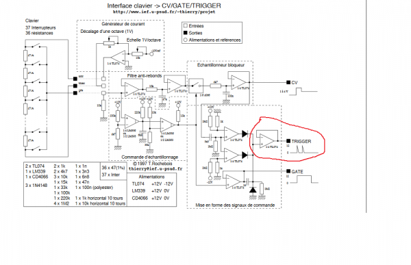
the keyboard circuit is apparently misbehaving. 
I have it breadboarded and i am making the contact between resistor chain and the buss with a simple wire to test it out.
some times i get a constantly on TRIGGER 12 v output signal ,with no key pressed.Other times, instead, it stays off until i press a key, as expected. The GATE works perfectly at least.
The major issue boils down to the keyboard buss contact.though. At times, the contact between the resistor chain and the buss makes random notes or a slightly fluctuating frequency. Other times,rarer, is perfect.
I wonder what's going on. Any ideas ?
i made everything by the book, except subbing the CD4066 with a CD4016.
many thanks !
| Description: |
|
| Filesize: |
47.29 KB |
| Viewed: |
614 Time(s) |
| This image has been reduced to fit the page. Click on it to enlarge. |
|
|
|
|
Back to top
|
|
 |
yusynth

Joined: Nov 24, 2005
Posts: 1314
Location: France
|
| Posted: Thu Dec 01, 2016 11:55 am Post subject:
|
|
|
I am not sure I understood. You are not using a real keybed but actually use a simple wire that you make contact with resistor chain handling the wire in your hand ? If this so then it is prone to capture main supply hum (holding the wire between finger) which may trigger randomly things.
Have you tried with a shielded wire (with shield grounded) ?
_________________
Yves |
|
|
Back to top
|
|
|
alanwilder81
Joined: Sep 03, 2016
Posts: 310
Location: italy
|
| Posted: Thu Dec 01, 2016 12:11 pm Post subject:
|
|
|
hey Yves,
i am using a crude CAT-5 cable connected from the buss, touching the different resistors of resistor chain. it's a rough method, quick and dirty i know.I dont have a shielded cable at hand,so i tried that way  |
|
|
Back to top
|
|
|
alanwilder81
Joined: Sep 03, 2016
Posts: 310
Location: italy
|
| Posted: Thu Dec 01, 2016 12:18 pm Post subject:
|
|
|
so you confirm it might trigger randomly. On "key press",it produces the desidered frequency, and on "key release", i often get a upper or lower note.
Almost never a clean and steady frequency though |
|
|
Back to top
|
|
|
Cfish

Joined: Feb 24, 2016
Posts: 477
Location: Indiana
|
| Posted: Thu Dec 01, 2016 1:45 pm Post subject:
|
|
|
The note shift on the end is probably switch bounce from the rough test method you are using ( wire doing a, make break, make break as you pull it away.) that will mess with the sample and hold. Will almost always produce a pitch fall off. Had that problem with one set of bass pedals that had really long open reed switches.
If the gate staying on coincides with the pitch issue, I would look at everything around the 2 opamps on the lower left. They are responsible fore the gate prior to the sample and hold. Loose ground would do it.
Sorry I can't help more, but I didn't use the LM339. I adjusted the bias to use TL072 in that location. I couldn't see a reason why not to. |
|
|
Back to top
|
|
|
alanwilder81
Joined: Sep 03, 2016
Posts: 310
Location: italy
|
| Posted: Sat Dec 03, 2016 2:14 pm Post subject:
|
|
|
hey Cfish,
thanks as ever.
i dont know how far you've gone with that keyboard circuit nor if you completed it.Time ago you said you only built the sample and hold part.
that said,it's well over my head to troubleshoot that circuit.
As for the frequency fall off thing that you described on key release. How did you fix it? it does it only occasionally
what puzzles me the most,tho,is the constantly on TRIGGER, reading around 8 V while the GATE works regularly between 0 and 12 V.
any further ideas ?
thanks |
|
|
Back to top
|
|
|
Cfish
Joined: Feb 24, 2016
Posts: 477
Location: Indiana
|
| Posted: Sat Dec 03, 2016 4:21 pm Post subject:
|
|
|
The random sample and hold issue may clear up when you are using an actual keyboard.
If the trigger is on, but the gate is working correctly. That is on the right hand side of the schematic.
Bottom right opamp is gate buffer. The 3 opamps over it in the same section are the trigger opamps.
I have not built that section yet, so I can't give you good advice there, except to check everything around those 3 opamps
It pretty much has to be there.
Edit. Took another look. Actually if you have voltage out all the time on the trigger, you probably need to look at the trigger output buffer opamp.
Check what trigger voltage looks like on its input. If it is a proper trigger puls there, the problem is at the output trigger opamp. |
|
|
Back to top
|
|
|
alanwilder81
Joined: Sep 03, 2016
Posts: 310
Location: italy
|
| Posted: Sat Dec 03, 2016 4:36 pm Post subject:
|
|
|
thanks Cfish,
since it's still breadboarded,i'll take it apart and re build and i'll see whats what. As for the keyboard, well, it's time to either get one from an old synthesizer or even from a toy keyboard , because, as you said the pitch problem might lay down to a crude testing method of mine.we will see.
thanks for the moment !! 
what have you been up to ?? |
|
|
Back to top
|
|
|
alanwilder81
Joined: Sep 03, 2016
Posts: 310
Location: italy
|
|
|
Back to top
|
|
|
Cfish
Joined: Feb 24, 2016
Posts: 477
Location: Indiana
|
| Posted: Sat Dec 03, 2016 4:56 pm Post subject:
|
|
|
| well that eliminates the output buffer being the problem |
|
|
Back to top
|
|
|
Cfish
Joined: Feb 24, 2016
Posts: 477
Location: Indiana
|
| Posted: Sat Dec 03, 2016 5:15 pm Post subject:
|
|
|
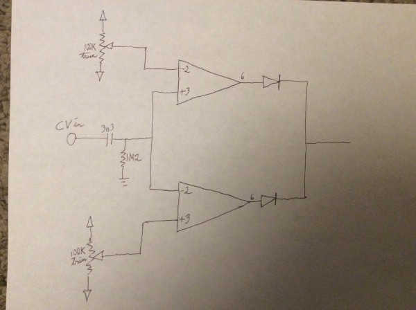
| I'm trying to grasp how the 2 comparators before the buffer produce an output puls. |
|
|
Back to top
|
|
|
gdavis
Joined: Feb 27, 2013
Posts: 359
Location: San Diego
Audio files: 1
|
| Posted: Sat Dec 03, 2016 6:44 pm Post subject:
|
|
|
| Cfish wrote: | | I'm trying to grasp how the 2 comparators before the buffer produce an output puls. |
The 3n3 cap and 1M2 resistor create a small negative or positive pulse whenever the CV changes suddenly. One comparator senses a negative going pulse and the other senses a positive going pulse. Together the comparators create a trigger pulse whenever the CV changes either up or down.
_________________
My synth build blog: http://gndsynth.blogspot.com/ |
|
|
Back to top
|
|
|
alanwilder81
Joined: Sep 03, 2016
Posts: 310
Location: italy
|
| Posted: Sun Dec 04, 2016 3:15 am Post subject:
|
|
|
| thanks Gdavis, i am starting to make sense of it.still the frigging trigger always on output is driving me nuts. |
|
|
Back to top
|
|
|
Cfish
Joined: Feb 24, 2016
Posts: 477
Location: Indiana
|
| Posted: Sun Dec 04, 2016 11:46 am Post subject:
|
|
|
Thanks gdavis
My real point of confusion is the reference voltages being supplied to the comparators. Couldn't they have just been referenced to ground??? |
|
|
Back to top
|
|
|
gdavis
Joined: Feb 27, 2013
Posts: 359
Location: San Diego
Audio files: 1
|
| Posted: Sun Dec 04, 2016 1:21 pm Post subject:
|
|
|
| Cfish wrote: | Thanks gdavis
My real point of confusion is the reference voltages being supplied to the comparators. Couldn't they have just been referenced to ground??? |
Oh! No, because the input pulses are referenced to ground so any small amount of noise would trigger it. They're referenced to slightly above ground and slightly below ground to create a threshold that the input pulses have to reach in order to create a trigger.
_________________
My synth build blog: http://gndsynth.blogspot.com/ |
|
|
Back to top
|
|
|
Cfish
Joined: Feb 24, 2016
Posts: 477
Location: Indiana
|
| Posted: Sun Dec 04, 2016 1:34 pm Post subject:
|
|
|
Thanks gdavis
Makes since, thanks for your help. |
|
|
Back to top
|
|
|
Cfish
Joined: Feb 24, 2016
Posts: 477
Location: Indiana
|
|
|
Back to top
|
|
|
alanwilder81
Joined: Sep 03, 2016
Posts: 310
Location: italy
|
| Posted: Wed Dec 07, 2016 3:06 am Post subject:
|
|
|
thanks cfish,
so,did you complete the circuit this time around? as for the issue you mentioned, its impossible by now to make any comparisons between my work and yours,because of so many modifications you made to the original |
|
|
Back to top
|
|
|
Cfish
Joined: Feb 24, 2016
Posts: 477
Location: Indiana
|
| Posted: Wed Dec 07, 2016 11:57 am Post subject:
|
|
|
Hi alanwilder81
It's pretty much complete with a few changes.
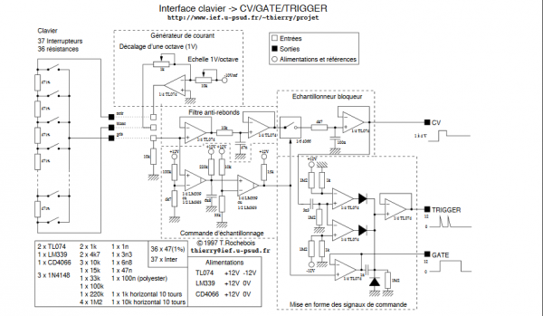
All you need to do to see which comparator is on, is check for voltage at the output of each comparator opamp, between the opamp and diode. Should be -v except for output puls. If one is on, the reference voltage to that comparator is not far enough off ground to consistently shut it off after a puls.
That's assuming there isn't just a small build error on the breadboard.
Also there is a line between the comparators and the output buffer going down to the gate. I would unhook that untill you get the problem ironed out. I left it out on mine all together at the moment. It is there to cause a retrigger when you play a patern on the same key. I will add it in. I just haven't yet.
If your still having problems I could try to do a quick private reference video on YouTube and list you to view it, if you have a YouTube account.
Once I got my head wrapped around how the comparators were working, this is a really easy circuit to diognose trouble with. Really not sure why I was having trouble seeing it to begin with. |
|
|
Back to top
|
|
|
|

 Forum index » DIY Hardware and Software » YuSynth