| Author |
Message |
Cfish

Joined: Feb 24, 2016
Posts: 477
Location: Indiana
|
 Posted: Sat Mar 19, 2016 9:54 am Post subject:
Easy analog synth project Posted: Sat Mar 19, 2016 9:54 am Post subject:
Easy analog synth project
Subject description: Mono synth project |
  |
|
Wanted to show a little project I put together.
Is a 16 note analog synth, using Ken Stones schematic using a 74c922 IC to matrix the keys
The EFM VCO1c schematic
And the single transistor VCA I have seen a few places on this sight.
Nothing fancy. But a great first synth project.
Will try to throw in a link to a YouTube video on the project.
https://youtu.be/N4v_UEWV_Z4


 [/img][/url] [/img][/url]
(Update) the key lag in the key matrix circuit talked about in this project was drastically improved by decreasing the capacitor values at pins 5 and 6. The data sheet recommends a x10 proportenment with a minimum 100n and 10n. When I tried it at the minimum values with a quick rigged set of momentary switches it worked well, but may require higher values for other switches.
Thanks for everybodies help with that little snag.
Last edited by Cfish on Sat Apr 23, 2016 4:38 pm; edited 2 times in total |
|
|
Back to top
|
|
 |
Cfish
Joined: Feb 24, 2016
Posts: 477
Location: Indiana
|
| Posted: Sat Mar 19, 2016 10:09 am Post subject:
|
|
|
The UJT in the VCO is available through many vendors on eBay, and I believe Newark has them available too.
I purchased all of my components on eBay. |
|
|
Back to top
|
|
|
PHOBoS

Joined: Jan 14, 2010
Posts: 5599
Location: Moon Base
Audio files: 705
|
| Posted: Sun Mar 20, 2016 11:09 am Post subject:
|
|
|
nice project,. sounds pretty good for such a simple circuit, although slightly out of tune in the higher octaves.
But the bass sounds great, might have to make me something like that myself. I think the only part I currently
don't have is the keyboard decoder IC.
Oh and what is the collector of the transistor in the decoder circuit supposed to be attached to, I assume the positive rail ?
_________________
"My perf, it's full of holes!"
http://phobos.000space.com/
SoundCloud BandCamp MixCloud Stickney Synthyards Captain Collider Twitch YouTube |
|
|
Back to top
|
|
|
Cfish
Joined: Feb 24, 2016
Posts: 477
Location: Indiana
|
| Posted: Mon Mar 21, 2016 6:07 am Post subject:
|
|
|
it tracked a little better once I sat down with a tuner and adjusted the trims.
I would say 3 usable octaves.
Yes the collector of the transistor for the gate ties to the positive rail. |
|
|
Back to top
|
|
|
Cfish
Joined: Feb 24, 2016
Posts: 477
Location: Indiana
|
| Posted: Mon Mar 21, 2016 12:24 pm Post subject:
|
|
|
Here is un update to what I have done with this project.
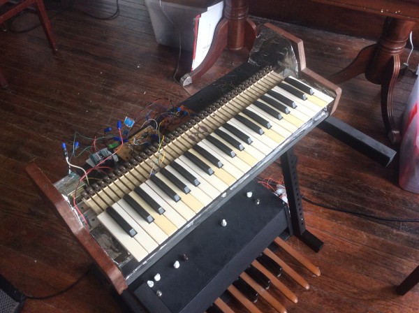
Instead of the 74c922 circuit to matrix the keys, I finally got a simple volt per octave key board circuit working.

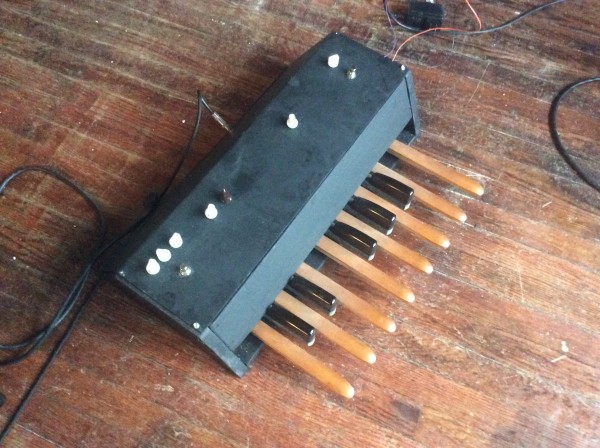
This got rid of my key lag issue and you can scale it to a larger keybed if you want. I'm using it in a set of bass pedals.
( UPDATE ) I used this in a set of bass pedals and a 2 octave controller all winter long, with no problems. Turns out the radiant heat in my house is very stable at 72 degrees. Spring came and the heat is off. The house got up to 78 degrees and the span drifted substantially.
I ordered some op-amps with better temperature drift ratings to try out.
I have high hopes for the OP177 op-amp. At a glance it appears it may plug right in the IC socket and minimize the drift issue. they are about 3 dollars each at DIGI-KEY
(Another update) the OP177 opamps were a great success.
Build it with what you have, but if you need it instrument perfect these OP177's are awesome.
I had to use the heat gun to get a drift I could register.
Last edited by Cfish on Wed Apr 27, 2016 12:25 pm; edited 2 times in total |
|
|
Back to top
|
|
|
L´Andratté

Joined: Sep 23, 2012
Posts: 150
Location: Hamburg, Germany
Audio files: 5
|
| Posted: Mon Apr 04, 2016 4:05 am Post subject:
|
|
|
Hey Cfish! Supernice synth circuit, you compiled there, I think it sounds very good/raw. I actually think I have to check it out myself! Need to get the 2646s first! Banzai says they have them.
Som3where in the video you mention a low pass filter, I didn´t get that (no native English/American speaker), would you explain?
Probably will use push buttons, need to find some playable and durable ones...
Thanks for posting  |
|
|
Back to top
|
|
|
Cfish
Joined: Feb 24, 2016
Posts: 477
Location: Indiana
|
| Posted: Mon Apr 04, 2016 11:26 am Post subject:
|
|
|
Thanks L'andratte. The low pass filter I was using was just a 100k poteonometer with a .47 uf capacitor to ground. Was wired like a guitar tone knob.
would love to see some posts here about your take on the project. Good luck with it. |
|
|
Back to top
|
|
|
Cfish
Joined: Feb 24, 2016
Posts: 477
Location: Indiana
|
|
|
Back to top
|
|
|
Cfish
Joined: Feb 24, 2016
Posts: 477
Location: Indiana
|
|
|
Back to top
|
|
|
Cfish
Joined: Feb 24, 2016
Posts: 477
Location: Indiana
|
| Posted: Fri Apr 08, 2016 5:25 pm Post subject:
|
|
|
To sum it all up
It works great for such an easy project.
It takes a few minutes to warm up the vco, then it stays pretty stable. I did use a matched pair of 2n3906s and bonded them together. Not sure if it helps in this particular situation or not. That's beyond my knowledge level.
I could get about 2 octaves in tune then it fell off quick. The one octave on the bass pedals is perfect on the tuner.
The trimmers on the resistor chain volt per octave key circuit I used in the pedals need to be 10 turn. I started with single turn and got it in tune. But it was a pain, and the gate signal was so touchy to get right. The 10 turns made things a lot easier.
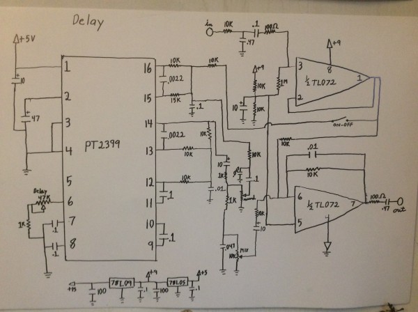
I increased the low pass filter capacitor values more than I ever have in the pt2399 delay circuit, and added another low pass on my input buffer.
I think it's my favorite delay circuit yet. It sounds warm and natural even at long delay times. |
|
|
Back to top
|
|
|
Cfish
Joined: Feb 24, 2016
Posts: 477
Location: Indiana
|
|
|
Back to top
|
|
|
Cfish
Joined: Feb 24, 2016
Posts: 477
Location: Indiana
|
|
|
Back to top
|
|
|
Grumble

Joined: Nov 23, 2015
Posts: 1294
Location: Netherlands
Audio files: 30
|
| Posted: Mon Jan 09, 2017 10:53 pm Post subject:
|
|
|
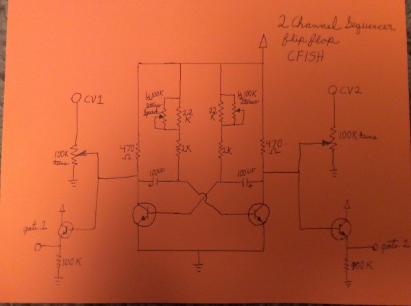
A ping pong sequencer? Whats that and what donyou do with it?  |
|
|
Back to top
|
|
|
Cfish
Joined: Feb 24, 2016
Posts: 477
Location: Indiana
|
|
|
Back to top
|
|
|
Cfish
Joined: Feb 24, 2016
Posts: 477
Location: Indiana
|
| Posted: Tue Jan 10, 2017 11:46 am Post subject:
|
|
|
Well, my memory wasn't so good.
LOL I apparently made the same mistake on both VCOs and can't seem to figure it out.
Have built that VCO schematic more than 10 times and never had it fail to work.
It should be obvious, however it's iluding me.
When I find it I'm gonna feel stupid!!! |
|
|
Back to top
|
|
|
Cfish
Joined: Feb 24, 2016
Posts: 477
Location: Indiana
|
| Posted: Tue Jan 10, 2017 12:51 pm Post subject:
|
|
|
Found it.
And yup, stupid. Flipped B1 and B2 on the UJTs. I kept checking that, and inverting it when I flipped the board back and forth. |
|
|
Back to top
|
|
|
Cfish
Joined: Feb 24, 2016
Posts: 477
Location: Indiana
|
| Posted: Sun Feb 05, 2017 7:26 pm Post subject:
|
|
|
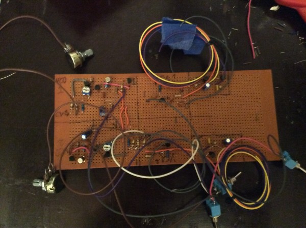
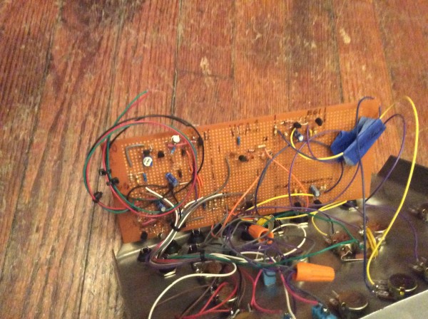
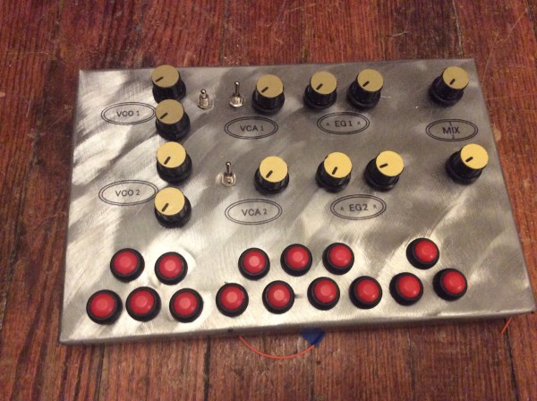
A little on the project using this concept.
All on one board, 2 VCOs 2 VCAs plus 2 Descrete EGs I posted in another place here.
Look at that board, a child could do it.
| Description: |
|
| Filesize: |
1.17 MB |
| Viewed: |
243 Time(s) |
| This image has been reduced to fit the page. Click on it to enlarge. |
|
| Description: |
|
| Filesize: |
1.17 MB |
| Viewed: |
249 Time(s) |
| This image has been reduced to fit the page. Click on it to enlarge. |
|
| Description: |
|
| Filesize: |
1.17 MB |
| Viewed: |
214 Time(s) |
| This image has been reduced to fit the page. Click on it to enlarge. |

|
|
|
|
Back to top
|
|
|
|

 Forum index » DIY Hardware and Software » Developers' Corner