| Author |
Message |
mph

Joined: Aug 25, 2007
Posts: 87
Location: France
|
|
|
Back to top
|
|
 |
piedwagtail

Joined: Apr 15, 2006
Posts: 297
Location: shoreditch
Audio files: 3
|
 Posted: Wed Nov 08, 2017 3:43 pm Post subject: Posted: Wed Nov 08, 2017 3:43 pm Post subject:
|
  |
|
I suggest you get some good quality breadboards and jumpers and physically test your circuit with some crocodile leads to the 4075.
Yes, it's some labour but in the end you own your design.
Fine tuning your inputs is very important. ARP were providing a solution to suit all tastes.
I've done the same with a 4023 but added fine CV control with attenuation, offset and gain. A send/return break and a 3080 VCA with attenuverter CV in the Resonance path.
R |
|
|
Back to top
|
|
|
mph
Joined: Aug 25, 2007
Posts: 87
Location: France
|
| Posted: Thu Nov 09, 2017 6:48 am Post subject:
|
|
|
Hi
thanks for the idea!
It would be nice to implement the VC Resonance to this filter.
Have you tried to get the feedback path after the hipass filter?
I'm wondering if that could be interesting...
Do you remember which schematic you used for the VCA?
I've seen the Craig Anderton's AMS-100 VCA VCD which seems perfect for a dirt style resonance control.
You're right, I'll breadboard the thing around the ARP module first. |
|
|
Back to top
|
|
|
piedwagtail
Joined: Apr 15, 2006
Posts: 297
Location: shoreditch
Audio files: 3
|
| Posted: Fri Nov 10, 2017 10:01 am Post subject:
|
|
|
Another reason to breadboard is that there are mistakes in the official service manuals for both the Odyssey and 2600 and by extension Verghese's work; that I've found so far.
Mistakes which have slipped into the work of kit providers.
R |
|
|
Back to top
|
|
|
mph
Joined: Aug 25, 2007
Posts: 87
Location: France
|
| Posted: Sat Nov 11, 2017 4:07 am Post subject:
|
|
|
You're right about breadboard; but I first thought this would be way simpler to hook up the 4075 VCF to a bit of circuit.
I don't know about errors in those ARP schematics... I hope I used at least the valid part of the schemos to draw the connections to the module.
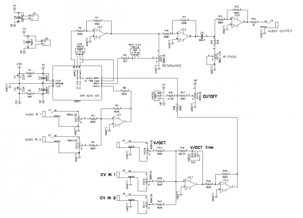
Thank you very much for the ideas, I've drawn a new version which includes the VC Resonance and the break-in jack. I don't know if a real send/return with an attenuator would be better.
That's a bit messy, and I will probably change the opamps to avoid VC and audio processing in the same opamp.
I've got to gather some parts then it will be breadboard fun 
edit: U4 is a CA3080
Last edited by mph on Fri Nov 17, 2017 10:54 am; edited 1 time in total |
|
|
Back to top
|
|
|
mph
Joined: Aug 25, 2007
Posts: 87
Location: France
|
| Posted: Thu Nov 16, 2017 5:23 am Post subject:
|
|
|
Hi
I've spent a lot of time struggling with my breadboards, trying to make the connections tight to the ARP module 
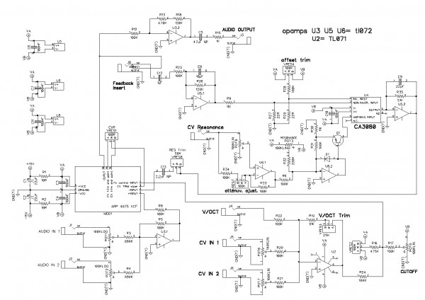
I've correctect many mistakes on my previous schematic, drawn too fast...
I've removed redundant buffers which caused some trouble with the resonance.
For testing purpose I've removed the whole CV resonance circuit, keeping this as a simple loop with a 100K pot and 25K trimmer in series.
I've tried inverting and non inverting configurations to send the signal into the resonance path, but none worked: the overall ouput was very weak with no resonance at all; I can't figure why...
I remember on the Odyssey you can still hear the input signal while at max resonance, it's quite interesting and musical, but the sine from the resonance was also strong and usable as a limited VCO.
So I had lowered the input signal and boosted the general output; this give a nice balance between the input signal and the resonance on itself. This sounds good but the resonance remains a bit quieter than the input signal.
Am I on the right way to adapt this VCF?
Honestly having an input gain of 0.14 seems strange, but if I raise this gain, I'm not able to have a good balance between resonance and input signal.
With an input gain of 1 the signal would be four times the amplitude of the resonance, so I cheated and lowered the input, then boosted the output stage.
I've also removed the HiPass part, it sucked too much signal. Maybe I'll have a look at an active HiPass circuit instead of passive like in the Odyssey schematic...
I'll try to add the CV resonance on the breadboard quickly!
Last edited by mph on Fri Nov 17, 2017 10:54 am; edited 1 time in total |
|
|
Back to top
|
|
|
mph
Joined: Aug 25, 2007
Posts: 87
Location: France
|
|
|
Back to top
|
|
|
n.d

Joined: Dec 15, 2011
Posts: 52
Location: Talos IV
|
| Posted: Wed Apr 25, 2018 12:27 pm Post subject:
|
|
|
Great work!
Do you have a layout for this adapter?
Did you replace the "fat" pins? |
|
|
Back to top
|
|
|
mph
Joined: Aug 25, 2007
Posts: 87
Location: France
|
| Posted: Wed Apr 25, 2018 3:17 pm Post subject:
|
|
|
Thanks!
But I'm not satisfied with the feedback path insert, I think a full send/return TRS with attenuator would be more useful. I'll probably convert it to a third CV input later.
Also the VCA is tricky to setup, but it works pretty well and the module sounds like my memories of the original VCF when used in the Odyssey.
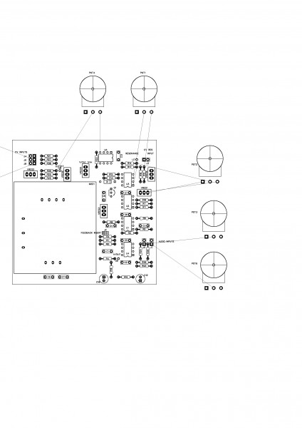
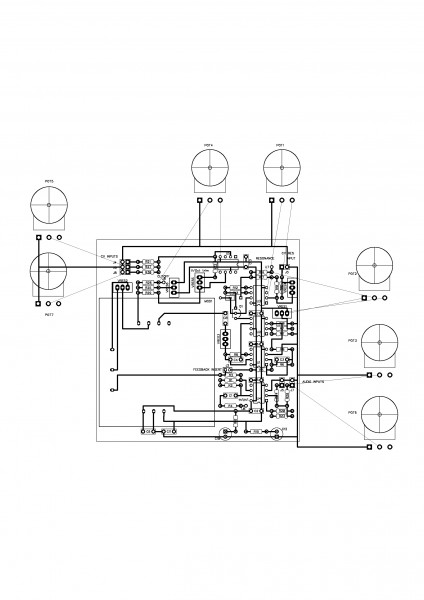
I didn't do a proper layout, I've mounted everything straight on perfboard and it has too many jumpers to be a real layout. It's quite big.
Also I wanted to keep the original pins, they are 2.54mm pitch, perfect for perfboard.
edit: I've just found a raw drawing I've used to build on perfboard.
No sure if it's completely accurate, it may be useful to draw a clean one.
| Description: |
|
| Filesize: |
431.1 KB |
| Viewed: |
313 Time(s) |
| This image has been reduced to fit the page. Click on it to enlarge. |
|
| Description: |
|
| Filesize: |
528.08 KB |
| Viewed: |
312 Time(s) |
| This image has been reduced to fit the page. Click on it to enlarge. |
|
|
|
|
Back to top
|
|
|
n.d
Joined: Dec 15, 2011
Posts: 52
Location: Talos IV
|
| Posted: Wed Apr 25, 2018 3:37 pm Post subject:
|
|
|
Great. Thanks for replying so quickly.
This is more than enough to work with. If and when I make a layout, I'll post it here. |
|
|
Back to top
|
|
|
|

 Forum index » DIY Hardware and Software