| Author |
Message |
tonewill
Joined: Aug 21, 2009
Posts: 135
Location: England
|
 Posted: Sat Mar 24, 2018 9:13 am Post subject:
Roland CR-78: Repair broken traces and pads Posted: Sat Mar 24, 2018 9:13 am Post subject:
Roland CR-78: Repair broken traces and pads |
  |
|
Hello,
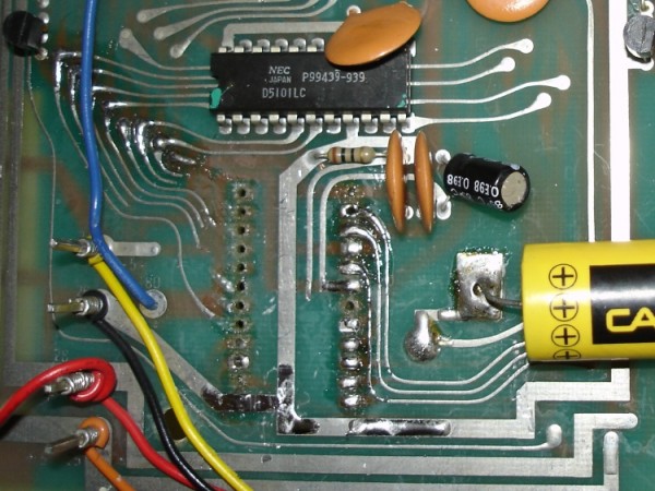
Can anyone please advice me on how to repair broken traces and IC pads? The board is double-sided and the traces are quite thin and close together. I want to make as good a job as I can. Is there a recommended kit or something I can buy? I'm okay with a soldering iron and have patients.
Thanks for any help. |
|
|
Back to top
|
|
 |
wackelpeter
Joined: May 05, 2013
Posts: 461
Location: germany
Audio files: 10
|
| Posted: Sat Mar 24, 2018 2:51 pm Post subject:
|
|
|
perhaps post some pics of the PCB and the broken traces... maybe someone has a clever idea... for example when it's broken between 2 components with legs were you can solder like diodes, resistors or some caps you can easily use a wire soldering between both Points...
I'm still having mine open since months, as i need to replace some IC's there and then will perhaps go to socket most of the IC's... and eventually re-cap the whole Thing...
_________________
https://soundcloud.com/bastian-j |
|
|
Back to top
|
|
|
tonewill
Joined: Aug 21, 2009
Posts: 135
Location: England
|
|
|
Back to top
|
|
|
ringroad
Joined: Feb 28, 2012
Posts: 38
Location: Coventry, UK
Audio files: 1
|
| Posted: Mon Mar 26, 2018 10:29 pm Post subject:
|
|
|
| You could try a silver conductive pen to redraw the tracks - never having used one myself I don't know how how accurate you can get with them, and looking at that you'll need to be good at it. It might just be better to attach wires. |
|
|
Back to top
|
|
|
tonewill
Joined: Aug 21, 2009
Posts: 135
Location: England
|
| Posted: Thu Mar 29, 2018 2:34 am Post subject:
|
|
|
Conductive pen isn't going to be fine enough. I've watched demos of these on youtube, much too crude.
If anyone can advice on repairing the tracks and pads or where to buy such things please let me know.
Thanks a lot. |
|
|
Back to top
|
|
|
DES

Joined: Feb 28, 2003
Posts: 794
Location: New Jersey
Audio files: 8
|
| Posted: Mon Apr 02, 2018 11:46 am Post subject:
|
|
|
Wow. Thats going to require some work, patience, and a steady hand. I would look for an IC socket with extended length pins...something like the old wire-wrap style sockets. The big issue hear is it seems to be a double-sided board with connections to the IC on both sides. If you find a suitable socket, insert it into the holes but make sure it is ~1/16 to 1/8" above the top of the pcb to allow you to thread/loop fine wire under the socket and around the pin (put a hook on the end of the wire feed it under the socket around a pin then squeeze/pinch it together then a dab of solder. Use fine bare wire...24-28 gauge, whatever you can get hold of. I prefer silver when possible. If you have stranded hookup wire try using the steands. Once connected to the pins, route them along the original circuit path til you get to the broken trace and attach. hold the wire in place with crazy glue or similar (note crazy glue gives off terrible fumes when heated!)
Another possibility...Get a thin flexible circuit made that has the ic pin hole layout on it. Make it just big enough to fit over the pins. If you can, design the flex circuit so there is a little extra pad at each pin so you can attach leads to it.
Good luck...thats going to be 'fun' repair!
_________________
Dave
www.davesneed.com |
|
|
Back to top
|
|
|
tonewill
Joined: Aug 21, 2009
Posts: 135
Location: England
|
| Posted: Tue Apr 03, 2018 8:54 am Post subject:
|
|
|
Thanks very much for all the info Dave.
Regarding the solder pads for the IC pins, can 'replacements' be had in some kind of repair kit? I just wan't to get it as good as possible. I searched for repair kits online but came up with over-the-top kits for people who do this kind of thing all the time.
Thanks again. |
|
|
Back to top
|
|
|
wackelpeter
Joined: May 05, 2013
Posts: 461
Location: germany
Audio files: 10
|
|
|
Back to top
|
|
|
tonewill
Joined: Aug 21, 2009
Posts: 135
Location: England
|
| Posted: Thu Apr 05, 2018 7:37 am Post subject:
|
|
|
Thanks for the extra info, very helpful. This may be the answer if repair pads aren't available in small quantities. Dave mentioned the longer pin sockets also and those are available on ebay. I was hoping to make it look as near original as possible but it's looking less likely.
Thanks again. |
|
|
Back to top
|
|
|
DES
Joined: Feb 28, 2003
Posts: 794
Location: New Jersey
Audio files: 8
|
| Posted: Mon Apr 09, 2018 6:17 am Post subject:
|
|
|
There was a company that used to make a trace repair kit..can't remember the name...and while you could replace individual pads on ICs, it was a pain to keep the pads in place while soldering especially if there were traces running between pads. Also you might be able to find the flexible IC circuits as very thin pcb material instead of the kapton/brownish flexible circuit material. Maybe in proto-typing supplies?
Saw a couple suppliers of wire wrap ic sockets on Amazon...Jameco has them too. CircuitMedic has kits though pricey from them...looks like JanelOnline sells some of the CircuitMedic stuff cheaper. You could look at adhesive copper tape and a sharp xacto knife...just watch your solder temp.
_________________
Dave
www.davesneed.com |
|
|
Back to top
|
|
|
tonewill
Joined: Aug 21, 2009
Posts: 135
Location: England
|
| Posted: Tue Apr 10, 2018 3:20 pm Post subject:
|
|
|
| Thanks for the extra info. I overlooked it on an earlier post but I'm not sure what the 'flexible IC circuits' are, are they circuits you get made to spec like normal circuits boards or are we talking about something else? |
|
|
Back to top
|
|
|
|

 Forum index » DIY Hardware and Software » The Repair Shop