| Author |
Message |
MapacheRaper

Joined: Feb 15, 2018
Posts: 166
Location: Spain
|
 Posted: Sat Sep 29, 2018 12:21 am Post subject:
How to mod Nicolas LFOs to Synch Posted: Sat Sep 29, 2018 12:21 am Post subject:
How to mod Nicolas LFOs to Synch |
  |
|
Hi,
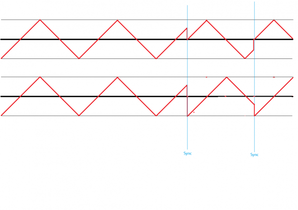
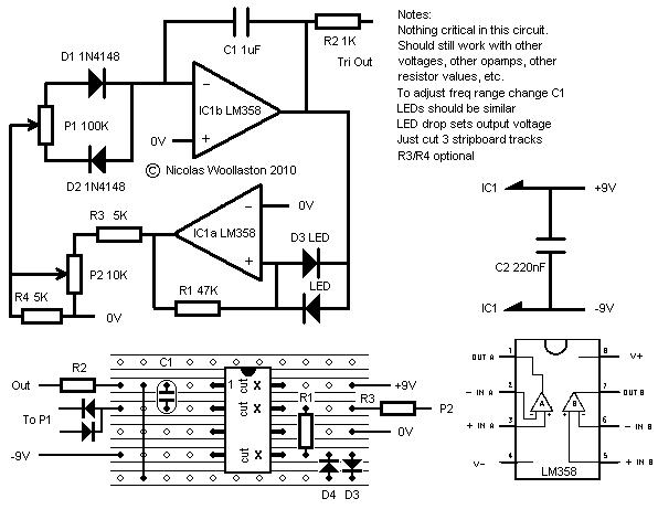
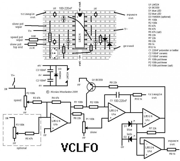
Im using this 2 homemade Nicolas3141 LFOs and they work nicely, but I would want to mod it so I can reset/synch them.
I guess I have to discarge the cap when the gate/trigger is up, isn´t?
Any suggestion of how to do it?
| Description: |
|
| Filesize: |
52.62 KB |
| Viewed: |
7053 Time(s) |
|
| Description: |
|
| Filesize: |
102.25 KB |
| Viewed: |
240 Time(s) |
| This image has been reduced to fit the page. Click on it to enlarge. |
|
|
|
|
Back to top
|
|
 |
gabbagabi

Joined: Nov 29, 2008
Posts: 652
Location: Berlin by n8
Audio files: 23
|
|
|
Back to top
|
|
|
MapacheRaper
Joined: Feb 15, 2018
Posts: 166
Location: Spain
|
| Posted: Sat Sep 29, 2018 2:46 am Post subject:
|
|
|
At 0 is perfect.
The question now is how do I short the cap with a gate/trigger easy peasy way? 
Maybe the gate is connected to the base of a transistor, and the colector and emisor are shorting the cap?
If the cap works in bipolar fashion I would need 2 transistors, 1 NPN and one PNP... isn´t?. But then, the gate would only activate one of the trannies... hmmm |
|
|
Back to top
|
|
|
gabbagabi
Joined: Nov 29, 2008
Posts: 652
Location: Berlin by n8
Audio files: 23
|
|
|
Back to top
|
|
|
gabbagabi
Joined: Nov 29, 2008
Posts: 652
Location: Berlin by n8
Audio files: 23
|
|
|
Back to top
|
|
|
MapacheRaper
Joined: Feb 15, 2018
Posts: 166
Location: Spain
|
| Posted: Sat Sep 29, 2018 9:01 pm Post subject:
|
|
|
Thanks for taking the time to explain and simulate it.
Im not sure why an opamp is needed at the gate´s in. To keep things simple couldn´t work just a 100k resistance to the base of the transistor?
So gate in>100k R>base tranny>which shorts the timer cap
I have the circuits in tiny PCBs that can´t allocate another opamp  |
|
|
Back to top
|
|
|
Ricko
Joined: Dec 25, 2007
Posts: 251
Location: Sydney, Australia
Audio files: 27
|
| Posted: Sat Sep 29, 2018 11:52 pm Post subject:
|
|
|
| Semi off topic. For another approach, search for my old post on "Kick Sync" which can add synch to any VCO because it works externally. |
|
|
Back to top
|
|
|
gabbagabi
Joined: Nov 29, 2008
Posts: 652
Location: Berlin by n8
Audio files: 23
|
|
|
Back to top
|
|
|
PHOBoS

Joined: Jan 14, 2010
Posts: 5599
Location: Moon Base
Audio files: 705
|
|
|
Back to top
|
|
|
gabbagabi
Joined: Nov 29, 2008
Posts: 652
Location: Berlin by n8
Audio files: 23
|
| Posted: Sun Sep 30, 2018 5:27 am Post subject:
|
|
|
poser! posting something that is called "super concert" to the nicolas lfo 
MapacheRaper, if there is to little space to make additions, why do not leave the circuits as they are, make a nice frontpanel for them. These are maybe one of the first circuits that u have build, may it is nice to keep them original, some modulators will be always handy.
In fact u will miss more in the future like sinus and inverted ramp, the triangle out is not buffered, the signal is not 10Vpp.
And then start building something more complete and leave a little more space?
or, make a more complete daugther board where u include all this, with a little help from ur friends here? |
|
|
Back to top
|
|
|
MapacheRaper
Joined: Feb 15, 2018
Posts: 166
Location: Spain
|
| Posted: Wed Oct 03, 2018 12:02 am Post subject:
|
|
|
Wow, thanks for all the suggestions, Guys!.
@Ricko. How to add sync to a VCO was one of my next questions... Im digging it. Thanks!!
@Gabba. That miniPCB seems superfeasible. I will try it. I prefer to update the circuits that to left museum reliquics . I plan to sync with standard 5v gates (does it mean I can use just the gate>100K resis>base transistor> that shorts timer cap?). Aanyway I´ll try both, I guess. Danke, maestro!!
@Phobos, thanks for the circuit. Im studing it . |
|
|
Back to top
|
|
|
gabbagabi
Joined: Nov 29, 2008
Posts: 652
Location: Berlin by n8
Audio files: 23
|
| Posted: Thu Oct 04, 2018 4:32 am Post subject:
|
|
|
please test it before on breadboard and let me know if it works, may u need to raise the value of the cap to lets say one or two nF
and, eventhougth i repeat myself, u will miss more in the future like sinus and inverted ramp, the triangle out is not buffered, the signal is not 10Vpp
may u consider a bigga daughterboard whith a quad-o-pamp? |
|
|
Back to top
|
|
|
PHOBoS
Joined: Jan 14, 2010
Posts: 5599
Location: Moon Base
Audio files: 705
|
| Posted: Thu Oct 04, 2018 11:22 am Post subject:
|
|
|
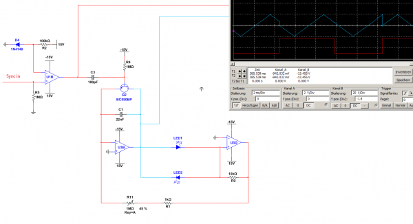
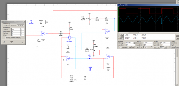
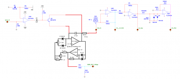
excuse me for dropping the schematics without any further explanation, I had a bit of a cold (actually still do). The first one was
designed for the EK2100 and works on a dual supply. You can find more info about that one here. The second one is part of a modified
"Super Concert" toy keyboard which works on a single supply. I only posted that one for the part in the top right corner and you can
find some info about it here.
They both use a LFO similar to the nicolas one to which I added different gating options. The top (EK2100) circuit uses a switch to
choose which gating option but the LFO section is a bit more complicated because of the dual supply. The other circuit uses a mux
which makes thing look a bit more complex but the LFO is more recognizable. Both of them are controlled through the non-inverting
input of one of the opamps. I don't think this method will be useful for syncing, but maybe you can do something similar with the
inverting input of the opamp that the capacitor is connected to (the integrator). g.gabba's method of directly shorting the cap might
work better though.
Anyway, it reminded me of those two circuits so maybe you'll find something useful in there
_________________
"My perf, it's full of holes!"
http://phobos.000space.com/
SoundCloud BandCamp MixCloud Stickney Synthyards Captain Collider Twitch YouTube |
|
|
Back to top
|
|
|
MapacheRaper
Joined: Feb 15, 2018
Posts: 166
Location: Spain
|
| Posted: Wed Oct 10, 2018 1:31 am Post subject:
|
|
|
I only grasp the surface of what you say, but I find it fascinating. Studing the circuit and your words will bring a lot of new electronic understanding and new ideas... Thanks for your explanation, Phobos!!
@Gabba. I have been building a Rampage and it works!!!. Fuck yea!!. Im overblown with the possibilities... So I haven´t had time to develop the board yet, but I will try in some moment and report, dude
Thanks!! |
|
|
Back to top
|
|
|
gabbagabi
Joined: Nov 29, 2008
Posts: 652
Location: Berlin by n8
Audio files: 23
|
| Posted: Wed Oct 10, 2018 5:54 am Post subject:
|
|
|
take a deep breath and relax
did the Sync-circuit has worked on breadboard? and now u are going on to build the daugtherboard?
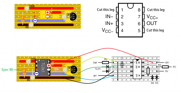
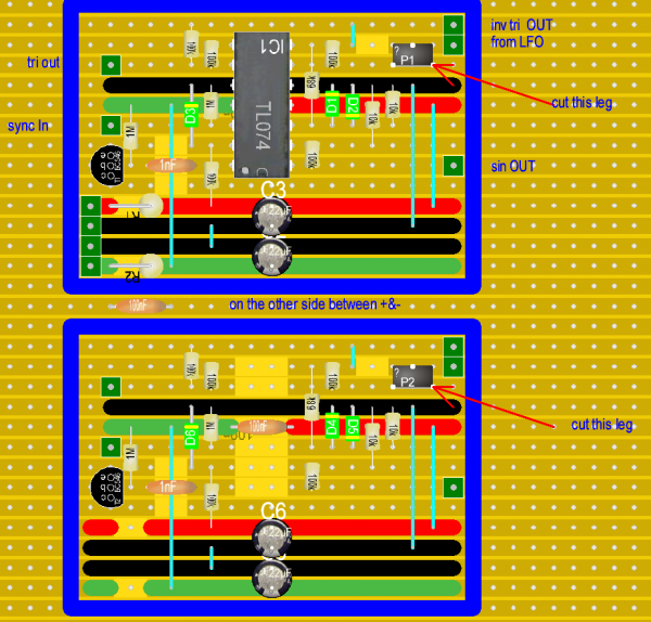
Well may u would consider something more phuture proof?
like this?
| Description: |
|
| Filesize: |
146.38 KB |
| Viewed: |
245 Time(s) |
| This image has been reduced to fit the page. Click on it to enlarge. |
|
| Description: |
|
| Filesize: |
139.6 KB |
| Viewed: |
206 Time(s) |
| This image has been reduced to fit the page. Click on it to enlarge. |
|
|
|
|
Back to top
|
|
|
MapacheRaper
Joined: Feb 15, 2018
Posts: 166
Location: Spain
|
| Posted: Wed Oct 10, 2018 11:42 pm Post subject:
|
|
|
This forum has few users but top quality ones... You have done a full-on LFO here.
That will be my next LFO build for sure.
I like how it exudes that is a labor of love... How much time did you employ?. Did you study EE?
In any case I think you should totally post it in the official nicolas LFO thread for more users to find it.
Thanks!! |
|
|
Back to top
|
|
|
|

 Forum index » DIY Hardware and Software