| Author |
Message |
xGx
Joined: Feb 11, 2019
Posts: 10
Location: USA
|
 Posted: Thu Jul 18, 2019 11:04 am Post subject:
Power supply with more current? Posted: Thu Jul 18, 2019 11:04 am Post subject:
Power supply with more current?
Subject description: 3 or 4 amps |
  |
|
| Hello, I am working on a project that has several circuits, and I had intended to power them all using a MFOS + / - 12V Wall Wart Power Supply with the suggested 12 VAC 1000 mA Wall Wart. However, I realized that one circuit requires 3 or 4 amps. Is there a way I can adapt the Wall Wart Power Supply to provide more current, for example by using a different wall wart and regulators? Would I need to change any other components / values? I have looked around, but it seems like most beginner DIY bipolar power supply projects provide 1 - 2 amps. It would be great if I could use the existing Wall Wart PCB. Thank you so much for your help! |
|
|
Back to top
|
|
 |
PHOBoS

Joined: Jan 14, 2010
Posts: 5599
Location: Moon Base
Audio files: 705
|
Posted: Sun Jul 21, 2019 4:44 am Post subject:
Re: Power supply with more current?
Subject description: 3 or 4 amps |
|
|
 
Is it really just one single ciruit or a combination of ciruits ? 3~4 amps is quite a lot. For a standard linear regulator, which is used in the MFOS wall wart PSU,
it is advised to have an input voltage that is 3V higher than the output. That would be 9-12 Watts that's dissipated in heat, if a voltage regulator could handle
that current in the first place. There are some linear regulators that can handle more current but they can be harder to find for negative voltages.
It is also possible to add a power transistor for more current but you will still have a lot of energy loss in heat. If it's not a single circuit you could use several
regulators powered by the same unregulated DC voltage to spread the power consumption and heat. So, In theory if you can find suitable regulators you could
use the MFOS supply but you will need some BIG heatsinks (and more capacitors). Finding a wall wart for that kind of current might get difficult too.
A better option would probably be a switched supply which can usually handle a lot more current with less loss but that depends a bit on the circuit.
_________________
"My perf, it's full of holes!"
http://phobos.000space.com/
SoundCloud BandCamp MixCloud Stickney Synthyards Captain Collider Twitch YouTube |
|
|
Back to top
|
|
|
xGx
Joined: Feb 11, 2019
Posts: 10
Location: USA
|
Posted: Sun Jul 21, 2019 10:13 am Post subject:
Re: Power supply with more current?
Subject description: 3 or 4 amps |
|
|
Thank you for the welcome and the reply, PHOBoS!
The project is combination of several circuis:
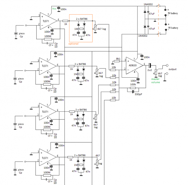
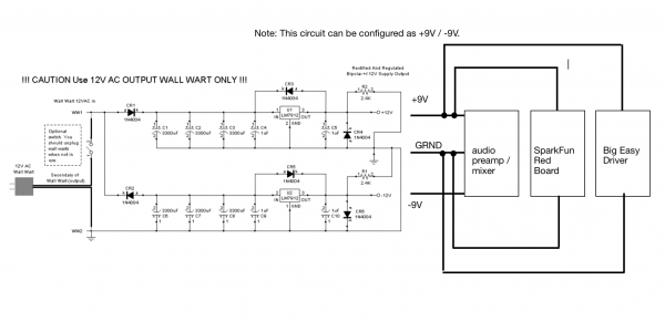
1. a piezo mixer / preamp requiring a bipolar +9 / -9V supply (schematic attached - note the original schematic had 5 channels, but I only need 4)
2. a SparkFun Red Board https://www.sparkfun.com/products/13975 requiring 7-15V;
3. a Big Easy Driver https://www.sparkfun.com/products/12859 requiring 8-35V driving this stepper motor https://www.sparkfun.com/products/13656
The Big Easy Driver documentation states the power supply "...should be a 6V to 30V, 3A (or more) power supply that is clean (low ripple)." http://www.schmalzhaus.com/BigEasyDriver/
Note SparkFun offers different requirements: "You can use any kind of power supply (desktop, wall adapter, battery power, etc.), but verify that whatever choice you go with is capable of providing up to 2A and falls in the range of 8V to 35V." https://learn.sparkfun.com/tutorials/big-easy-driver-hookup-guide
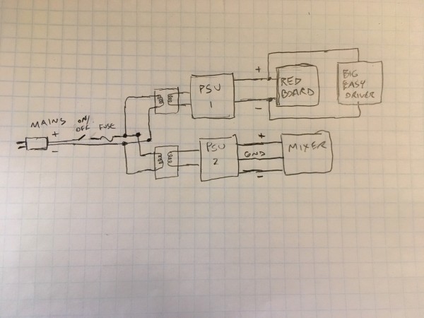
I was hoping to connect everything in parallel to one supply as in the attached block diagram (using the positive and ground of the biploar supply to power the Red Board and Big Easy Driver).
I have everything built and working; I am currently powering the Big Easy Driver with this supply https://www.amazon.com/gp/product/B073QTNF9F/ref=ppx_yo_dt_b_search_asin_title?ie=UTF8&psc=1 the RedBoard is powered via the USB of my laptop, and the mixer is powered by my bench power supply. I now want to mount everything permanently in my project box so that I have a single cord and on/off switch.
Not to complicate things, but the mixer schematic calls for +/-9V, whereas I was considering using +/-12V. The AD820 can handle up to +/-15V, so I think that is OK? If not, the MFOS power supply could be configured as +/-9V supply.... I just didn't want to be at the bottom of the voltage requirements, particularly for the Big Easy Driver.
Is there any chance the Wall Wart Power supply or something similar could work? It sounds like I may be able to get away with 2 amps if I go with SparkFun's requirements. Does that simply things? Do you think a linear supply is still plausible? I haven't yet found a good resource that introduces slightly more complicated power supply management, so any guidance would be much appreciated.
Thank you for your help!
[/img]
| Description: |
|
| Filesize: |
283.58 KB |
| Viewed: |
273 Time(s) |
| This image has been reduced to fit the page. Click on it to enlarge. |
|
| Description: |
|
| Filesize: |
198.72 KB |
| Viewed: |
368 Time(s) |
| This image has been reduced to fit the page. Click on it to enlarge. |
|
|
|
|
Back to top
|
|
|
JovianPyx

Joined: Nov 20, 2007
Posts: 1988
Location: West Red Spot, Jupiter
Audio files: 224
|
| Posted: Sun Jul 21, 2019 10:31 am Post subject:
|
|
|
It looks like the current hog is the Big Easy Driver which wants 3 amperes.
In my opinion, the Big Easy Driver needs it's own PSU. It would be unwise to drive all three circuits from one supply. I would create a 3 ampere supply for the Big Easy Driver and use a separate supply for the other two. The mixer should need very little current. The Red Board also, I'd predict fairly low current. LM350T is a 3 ampere regulator which could be used for the Big Easy Driver. Note that your transformer for this needs to supply at least 3000 mA. You might not be able to find a wall-wart transformer that provides that much current. It's voltage should be about 12 volts AC for a 9 volt regulator. If the input DC voltage is more than 12, you will experience more heat coming from the regulator. I would also plan on a substantially sized heat sink for it.
The Big Easy Driver needs to dump large currents into the stepper motor coils and could push noise back into it's supply. Using a separate power supply for it will help quash noise that could easily come from it.
_________________
FPGA, dsPIC and Fatman Synth Stuff
Time flies like a banana.
Fruit flies when you're having fun.
BTW, Do these genes make my ass look fat?
corruptio optimi pessima
|
|
|
Back to top
|
|
|
PHOBoS
Joined: Jan 14, 2010
Posts: 5599
Location: Moon Base
Audio files: 705
|
| Posted: Sun Jul 21, 2019 11:23 am Post subject:
|
|
|
| JovianPyx wrote: | In my opinion, the Big Easy Driver needs it's own PSU. It would be unwise to drive all three circuits from one supply.
..
The Big Easy Driver needs to dump large currents into the stepper motor coils and could push noise back into it's supply. Using a separate power supply for it will help quash noise that could easily come from it. |
Yep, I agree.
Keep the power for those steppers as far away from any audio circuits. On the plus side that part only needs a positive supply
and you could get regulators for that if needed (like the LM350T JovianPyx mentioned).
I also think the wall wart supply might not be ideal with such uneven loads on positive and negative rails. It would probably be better
to use 2 seperate transformers. So either way you'd need more that one supply.
_________________
"My perf, it's full of holes!"
http://phobos.000space.com/
SoundCloud BandCamp MixCloud Stickney Synthyards Captain Collider Twitch YouTube
Last edited by PHOBoS on Sun Jul 21, 2019 12:34 pm; edited 1 time in total |
|
|
Back to top
|
|
|
JovianPyx
Joined: Nov 20, 2007
Posts: 1988
Location: West Red Spot, Jupiter
Audio files: 224
|
| Posted: Sun Jul 21, 2019 11:55 am Post subject:
|
|
|
Oh and for the Big Easy Driver PSU, I would use on with a single secondary coil transformer feeding a full-wave rectifier. No sense throwing away half of the AC cycles.
_________________
FPGA, dsPIC and Fatman Synth Stuff
Time flies like a banana.
Fruit flies when you're having fun.
BTW, Do these genes make my ass look fat?
corruptio optimi pessima
|
|
|
Back to top
|
|
|
xGx
Joined: Feb 11, 2019
Posts: 10
Location: USA
|
|
|
Back to top
|
|
|
JovianPyx
Joined: Nov 20, 2007
Posts: 1988
Location: West Red Spot, Jupiter
Audio files: 224
|
| Posted: Sun Jul 21, 2019 5:25 pm Post subject:
|
|
|
That depends on how close to the 3 amperes the Big Easy Driver goes. If there is enough current headroom, the Red Board could work. If not, it could operate erratically.
I don't know how much current the Red Board needs and I don't know how much headroom the Big Easy Driver allows with a 3 amp supply.
_________________
FPGA, dsPIC and Fatman Synth Stuff
Time flies like a banana.
Fruit flies when you're having fun.
BTW, Do these genes make my ass look fat?
corruptio optimi pessima
|
|
|
Back to top
|
|
|
PHOBoS
Joined: Jan 14, 2010
Posts: 5599
Location: Moon Base
Audio files: 705
|
| Posted: Mon Jul 22, 2019 7:22 am Post subject:
|
|
|
| xGx wrote: | | Is the attached sketch at all close? Mains power feeding two transformers in parallel.... one for a unipolar PSU and one for a bipolar PSU? The unipolar would maybe use the LM350T, and the bipolar perhaps the LM317 and LM337? |
Looks good to me but I would add a seperate fuse for each PSU, reason being that the fuse needs to be rated high enough to protect PSU1
which won't offer a lot of protection for PSU2. I'd also use an extra fuse for the Big Easy driver as an extra protection. Also you might want
to use a double pole switch for the mains power just for extra safety.
btw I think that for PSU1 a switched supply would work great, it's probably cheaper, smaller and weighs less, while being also more efficient
so it produces less heat. Actually that's what you have been using so far 
_________________
"My perf, it's full of holes!"
http://phobos.000space.com/
SoundCloud BandCamp MixCloud Stickney Synthyards Captain Collider Twitch YouTube |
|
|
Back to top
|
|
|
xGx
Joined: Feb 11, 2019
Posts: 10
Location: USA
|
| Posted: Wed Aug 14, 2019 9:11 am Post subject:
|
|
|
| Quote: | I think that for PSU1 a switched supply would work great, it's probably cheaper, smaller and weighs less, while being also more efficient
so it produces less heat. |
Thanks PHOBoS! Finally finding some time to get back to this. So if PSU1 is a switched supply and PSU2 is the MFOS Wall Wart Power Supply, how would they "combine?" In the sketch above they connect between the fuse and the primaries, but a SMPS is designed differently (i.e., the transformer is in a different place, right?).
Also, it occurred to me that the MFOS WWPS wouldn't work with the above sketch since the wires coming out of the wall wart are (I think) the secondary windings, the primaries being in the wart part.
Another issue is I have not been able to find a reliable schematic for a 12V 4A SMPS.... any ideas for where to find one?
I'm also open to other ideas.... again I need a + / - 9V bipolar supply (I think + / - 12V would be OK) for the audio preamp and mixer, and a 12V, 4amp supply for the Red Board / Big Easy Driver / stepper motor.
I guess I could build the MFOS supply and then purchase a SMPS and have two switches and two plugs, but I was hoping to avoid that.
Thank you! |
|
|
Back to top
|
|
|
JovianPyx
Joined: Nov 20, 2007
Posts: 1988
Location: West Red Spot, Jupiter
Audio files: 224
|
| Posted: Thu Aug 15, 2019 1:05 pm Post subject:
|
|
|
Hmmm. My understanding of SMPS is that an oscillator is used to generate an input AC voltage to a transformer. The frequency is higher than 50Hz or 60 Hz to keep the size and weight of the transformer lower (50 kHz to 1 MHz). Note that the higher the switching frequency, the easier it is to filter out the switching noise. The transformer is fed a rather low voltage of AC from a DC source and a transistor "interrupter". The voltage can then be increased as high as 300 volts by the transformer. The output voltage is controlled by using phase control of the AC voltage fed to the transformer. The last stage is to use another transformer to lower the voltage to something useful. This is generally the design used in PC power supplies, but there can be many ways to design SMPS, I described only one.
Personally, I don't like to play around with voltages that high. I would buy a commercial SMPS rather than try to build one. I would attempt it only if the specs of the design you're trying to build do not include voltages that high. Please be careful, this could be a dangerous thing while trying to build and troubleshoot. I would seriously suggest purchasing this piece of gear from a commercial source.
_________________
FPGA, dsPIC and Fatman Synth Stuff
Time flies like a banana.
Fruit flies when you're having fun.
BTW, Do these genes make my ass look fat?
corruptio optimi pessima
|
|
|
Back to top
|
|
|
PHOBoS
Joined: Jan 14, 2010
Posts: 5599
Location: Moon Base
Audio files: 705
|
| Posted: Thu Aug 15, 2019 3:53 pm Post subject:
|
|
|
Yeah I agree with Scott, I wouldn't try to build the SMPS myself, unless you really really REALLY want to.
Could just use the one you already have (unless you need it for something else) just keep in mind that if you
would build it in a case it needs some ventilation.
An AC wallwart is just a transformer, with a (thermal)fuse if it is a proper one. So you can just use a transformer
for that, just make sure everything is properly insulated. That's one of the main advantages of using a wallwart,
you don't have to deal with the mains part and it's already in an enclosure.
If you have enough space there is an easy solution. Use a socket strip and plug in a wallwart and a SMPS, wire that
to a switch. You could even use one of those mains inlets with a build in fuse and switch, something like this.
_________________
"My perf, it's full of holes!"
http://phobos.000space.com/
SoundCloud BandCamp MixCloud Stickney Synthyards Captain Collider Twitch YouTube |
|
|
Back to top
|
|
|
xGx
Joined: Feb 11, 2019
Posts: 10
Location: USA
|
|
|
Back to top
|
|
|
blue hell
Site Admin

Joined: Apr 03, 2004
Posts: 24083
Location: The Netherlands, Enschede
Audio files: 278
G2 patch files: 320
|
| Posted: Sun Aug 18, 2019 8:31 am Post subject:
|
|
|
Genral idea will work.
add step 10 (or a little earlier better :-) ):
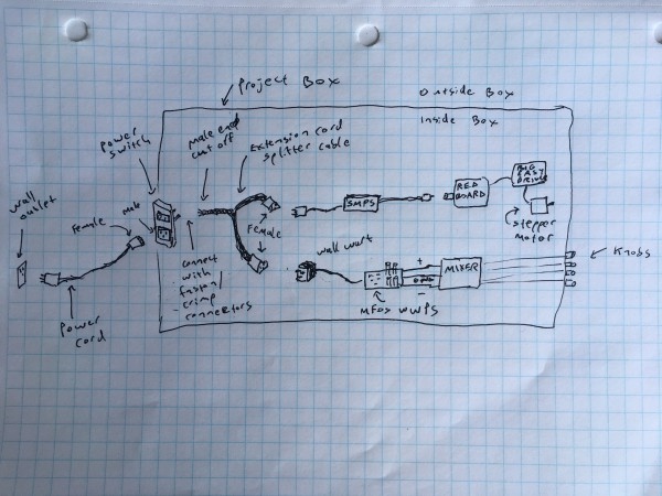
re 4. and 6. and so, use shrink wrap tubing over the solder connections of the mains wires, and make it so that the mains wires can't move anywhere even when a single failure occurs (like a not-so-good solder connection comming loose, or the device falling down from some height, stuff like that) - tie wraps may work well for that.
add step 11:
In the hand drawn schematic above, on the secondary sides of the supplies: connect '-' of PSU1 to 'GND' of PSU2 close to the PSU's (or otherwise they'll either float with regard to each other or there will be a ground connection anyway trough other connection not drawn but in a less defined way).
_________________
Jan
also .. could someone please turn down the thermostat a bit.
 |
|
|
Back to top
|
|
|
PHOBoS
Joined: Jan 14, 2010
Posts: 5599
Location: Moon Base
Audio files: 705
|
| Posted: Sun Aug 18, 2019 10:49 am Post subject:
|
|
|
step 6: I'd use (insulated) faston/crimp connectors instead of soldering which is what those switches are designed for. Soldering directly to the
switch requires quite a bit of heat which could potentially damage it (depends a bit on the quality). You could also solder to those connectors
instead of crimping on the wires, but it can be a bit tricky.
step 8: not exactly sure how you are planning to do that. Those aren't mains sockets. I mean voltage wise yes but you can't plug something
like a wallwart in them. There might be cables for that purpose available though.
and yes, make sure everything is properly secured.
_________________
"My perf, it's full of holes!"
http://phobos.000space.com/
SoundCloud BandCamp MixCloud Stickney Synthyards Captain Collider Twitch YouTube |
|
|
Back to top
|
|
|
xGx
Joined: Feb 11, 2019
Posts: 10
Location: USA
|
|
|
Back to top
|
|
|
PHOBoS
Joined: Jan 14, 2010
Posts: 5599
Location: Moon Base
Audio files: 705
|
|
|
Back to top
|
|
|
xGx
Joined: Feb 11, 2019
Posts: 10
Location: USA
|
|
|
Back to top
|
|
|
PHOBoS
Joined: Jan 14, 2010
Posts: 5599
Location: Moon Base
Audio files: 705
|
| Posted: Wed Aug 21, 2019 7:07 pm Post subject:
|
|
|
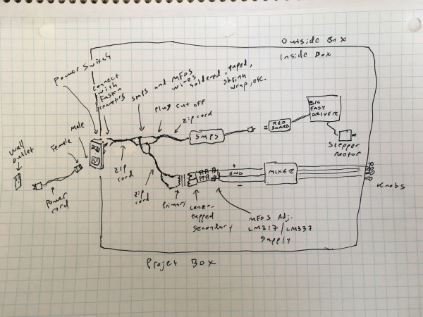
LM317/LM337 supply with an actual center-tapped transformer is an improvement over the standard wallwart supply
but does require you to wire up a transformer. A toroidal type might be the safest to use and easy to mount with the
correct hardware.
| Quote: | | 4. Solder the positive and ground of the SMPS supply and the MFOS supply together |
Only connect the GND together, at least if you want the mixer to be connected in some way to the stepper circuit otherwise
you don't need to connect anything together.
For the rest that should all work.
I am curious what you are working on.
_________________
"My perf, it's full of holes!"
http://phobos.000space.com/
SoundCloud BandCamp MixCloud Stickney Synthyards Captain Collider Twitch YouTube |
|
|
Back to top
|
|
|
mph

Joined: Aug 25, 2007
Posts: 87
Location: France
|
| Posted: Fri Aug 23, 2019 1:37 pm Post subject:
|
|
|
Hello
If you need a 5Amp PSU why don't you use the same regulator for each rail?
A simple pair of LM338, link them as you would do with 2x9V batteries to achieve symmetrical output.
V+
0 linked to the second V+
second 0 (which became V-)
I think it's better to use the same regulator on each rail because they will behave the same way under load. |
|
|
Back to top
|
|
|
xGx
Joined: Feb 11, 2019
Posts: 10
Location: USA
|
| Posted: Tue Aug 27, 2019 8:43 am Post subject:
|
|
|
| Quote: | Only connect the GND together, at least if you want the mixer to be connected in some way to the stepper circuit otherwise
you don't need to connect anything together. |
Thanks PHOBoS.... the stepper and the mixer do not need to interact. I just want them to turn on together. Don't both grounds and both hot wires need to connect at the back of the switch? I was thinking I would solder the grounds together and put a faston crimp on the resulting joined wires to connect to the switch. Then do the same for the hot wires. Maybe you are saying I can just put the two ground wires in one faston connector and the two hot wires in another faston connector, and not solder them at all? Just attach the two faston crimps to the switch?
Speaking of the switch, many of these inlet modules come with a 5A fuse. Will that be enough headroom considering the stepper wants 3 or 4 amps, and my SMPS is 12V, 5A? https://www.amazon.com/gp/product/B073QTNF9F/ref=ppx_yo_dt_b_search_asin_title?ie=UTF8&psc=1
Could I swap out the fuse in the switch for maybe a 6A or 8A? https://www.amazon.com/Ginsco-110pcs-5x20mm-Quick-Assorted/dp/B01CEB6B1Y/ref=sr_1_27?keywords=10A+fuse+20+x+5&qid=1566914219&s=gateway&sr=8-27
Or find a switch with a 10A fuse?
I am moving ahead with the simpler / safer method of the splitter cable and wall wart power supply, but I'd like to understand the points above for the next iteration. Thank you! |
|
|
Back to top
|
|
|
PHOBoS
Joined: Jan 14, 2010
Posts: 5599
Location: Moon Base
Audio files: 705
|
| Posted: Tue Aug 27, 2019 1:50 pm Post subject:
|
|
|
| Quote: | | Don't both grounds and both hot wires need to connect at the back of the switch? |
ah I think it's just a confusion because of terminology. Seems like you are talking about the mains side in which case you have a live and a neutral
connection. And an earth but you only need to connect that to any metal parts that could be touched (if there are any). At least your SMPS doesn't
appear to have a connection for earth. So yes, the neutral wires are connected together and to the mains input connector, and the live wires are
connected together and to the switch. Unless it is a double pole switch, which I doubt, then you can switch both live and neutral.
The fuse is probably even too large. The current you are talking about is on the secondary side, the current on the primary side will be much lower.
What stays the same is the power (Watts) although it's of course not 100% efficient so it will need more power than it puts out (in electricity).
If the SMPS is rated for 5A that's a total power of 5A x 12V = 60Watts. Since you seem to be in the US I assume the mains voltage is 120V so
60Watts / 120V = 0.5A. Of course 12V happens to be 1/10th of 120V so the current is also 1/10th. It's not completely accurate as you are not
dealing with a purely resistive load but it gives you an estimate. A 630mA fuse might just do it, you are not using it for its full 5A anyway. There could
be an inrush current that is too high for it so I would at least use a slow blow type fuse.
_________________
"My perf, it's full of holes!"
http://phobos.000space.com/
SoundCloud BandCamp MixCloud Stickney Synthyards Captain Collider Twitch YouTube |
|
|
Back to top
|
|
|
xGx
Joined: Feb 11, 2019
Posts: 10
Location: USA
|
|
|
Back to top
|
|
|
PHOBoS
Joined: Jan 14, 2010
Posts: 5599
Location: Moon Base
Audio files: 705
|
|
|
Back to top
|
|
|
|

 Forum index » DIY Hardware and Software » MusicFromOuterSpace.com designs by Ray Wilson