Joined: Jan 14, 2010 Posts: 5603 Location: Moon Base
Audio files: 705
Posted: Wed Jul 08, 2020 12:38 pm Post subject:
Quote:
what I haven't been able to figure out yet is how to make the connection (unless I use wires) at least not for 'corner cells'. I'll check some tiling patterns
to see if I can find a useful shape or maybe I can route some things through other boards. So for example if I need to get the signal to a cell in the top left corner,
which would be the position of e11, I could probably just route it through e0 and/or e10.
Ok, it looks like I don't need a fancy shaped PCB to make the connections and can indeed just route the signals through the other PCBs.
So that would be 36 connections per PCB, but I'll probably have to go with 10 pin connectors so make it 40. In that case I might add some
resistors to create a voltage anyway. I do have a SILly amount of SIL resistor networks so maybe I can do something with those.
GOL 4 CELL EPROM PCB CONNECTIONS.gif
Description:
Filesize:
78.14 KB
Viewed:
250 Time(s)
This image has been reduced to fit the page. Click on it to enlarge.
Joined: Jan 14, 2010 Posts: 5603 Location: Moon Base
Audio files: 705
Posted: Wed Jul 08, 2020 5:12 pm Post subject:
I'd probably start with a batch of 10, although the price per PCB (incl. shipping) is about the same for batches from 20 and up.
25 would be a nice grid of 5x5 boards = 10x10 cells.
Blue Hell wrote:
Hmm ..maybe you need some 4 bit flip flop thingie to store the actual cell states .. and let the EPROM machine 'just' do the control
I might have been thinking about it too complicated trying to change the status of the EPROM itself. This seems to be more of
a fake it untill you make it scenario which might be what you had in mind. Just change the outputs (which are fed back to the EPROM)
and on the next CLK it should sort itself out. I did come up with something that involves 4 extra XOR gates and 4 flipflops. Not sure yet
if it will actually work and I need to figure out what it would do if I use bicolored LEDs.
It will probably work fine with a different chip but I'd like to stick to what I have a lot of. Adding a schmitt trigger might help but that's yet another chip and
the circuit is already getting a bit larger than I initially had in mind. I do have a bunch of 555's I could use and 2 of those don't take up that much more
space as 1 74HC(T)74 and it might even be easier to route. I am not completely sure yet if I can use them in this circuit as I am also using the set input
on the flip-flop but that is combined with the /Q out so I guess using the reset on the 555 should do the same. _________________ "My perf, it's full of holes!" http://phobos.000space.com/ SoundCloudBandCampMixCloudStickney SynthyardsCaptain ColliderTwitchYouTube
Joined: Jan 14, 2010 Posts: 5603 Location: Moon Base
Audio files: 705
Posted: Sat Jul 11, 2020 7:42 am Post subject:
I messed around with this NAND circuit a bit. Works fine with a 4011, but didn't have any luck with a 74HC(T)00.
however, the good ol' 555 works like a charm and I like the idea of having some 555's in there.
I probably don't have enough depending on how many cells I want to make but it looks like I do
have close to 50 of them. I have to keep switching noise in mind though as all of them will be reset
at the same time. _________________ "My perf, it's full of holes!" http://phobos.000space.com/ SoundCloudBandCampMixCloudStickney SynthyardsCaptain ColliderTwitchYouTube
Joined: Jan 14, 2010 Posts: 5603 Location: Moon Base
Audio files: 705
Posted: Mon Jul 13, 2020 6:05 am Post subject:
why hadn't I thought of this (cube shape) yet
I need to figure out how to do it hardware wise. Since the boards will only have 4 cells, one board per side would probably be a bit too small, so that means
4 boards per side (24 in total seems doable, or 20 without the bottom). In that case boards should be able to connect to eachother on a flat surface and at
an angle. Of course there are angled connectors available but making the design so I can use both straight and angled connectors and have everything lined
up correctly might be a bit tricky. Maybe I could also add some sort of control circuit in the center to create random start patterns, or give it an umbilical cord.
hmm, at the very least that would require some shiftregisters, otherwise that would take 96 wires just to control the cells.
Joined: Jan 14, 2010 Posts: 5603 Location: Moon Base
Audio files: 705
Posted: Mon Jul 13, 2020 6:21 pm Post subject:
the difference a cube shape makes is that the corner cells have one less neigbour (7 instead of 8 ).
With the way I layed out the connections the result would be that the missing cells get replaced
with another corner cell. This means that the corner cells have more 'weight' and count as 2 cells.
So if 2 neighbouring corner cells are alive they will stay alive and if 3 corner cells are alive they will all die
as each cell sees 4 neighbors. (ignoring any other neighboring cells). Might be interesting and I could add
a jumper to disable it. I will have to change some things though as right now the CLK and V+ connections
would be shorted together. I wasn't happy with that anyway as I would like to make it so that the boards can
be rotated in any direction, which is also needed for a cube. problem right now is that that would require an
11 pin connector which isn't standard, but I could go larger or use several smaller connectors.
I just did some tests with the EPROM in circuit and it looks promising
So far I only tested with setting the A,B,C,D outputs and loading that back into the EPROM and I haven't tested
yet if it works with the other 12 inputs. I am not really expecting any problems with that though (famous last words).
I like those hands too .. hmm icosahedron? with triangular PCB's ... probably even nicer than a toroid _________________ Jan
also .. could someone please turn down the thermostat a bit.
Joined: Jan 14, 2010 Posts: 5603 Location: Moon Base
Audio files: 705
Posted: Tue Jul 14, 2020 12:50 am Post subject:
I was actually thinking about other platonic solids but the angles would be tricky, at least with any kind of connectors.
I'll think about it if I can get a cube working first. I am partial to the dodecahedron myself but the icosahedron is also very
nice and triangles could also be connected on a flat surface. _________________ "My perf, it's full of holes!" http://phobos.000space.com/ SoundCloudBandCampMixCloudStickney SynthyardsCaptain ColliderTwitchYouTube
I dont know .. can't you just bend the connectors .. say pin headers, mabe 90 degree ones ... into the correct angle? Then other side can just be 90 degrees so they lay flat on the PCB.
Hmm .. the other side needs some magic to then .. or maybe just not 90 degrees but just straight up.
But I think that I would just use wires .. on the inside .. but soldered on the outside .. although closing the "door" might be a little tricky then .. hmm .. with connectors it will be tricky too. _________________ Jan
also .. could someone please turn down the thermostat a bit.
Joined: Jan 14, 2010 Posts: 5603 Location: Moon Base
Audio files: 705
Posted: Tue Jul 14, 2020 6:34 am Post subject:
Bending might work but probably still tricky to get them correct and it's probably not wise to bend them once they are soldered in place.
Just using some wires to solder them together would indeeed be an easier solution in which case I'd probably do it in the same
way as the cube from that video, so on the outside. Another fancy option would be to 3D print some small blocks with screwholes that
have the correct angles to place in the corners and then mount the PCB's on to those. Connections could then be made on the inside
with some ribbon cables.
I am currently testing some other addresses (neighbors) and sofar it actually seems to be working. Not sure how well it will work with
multiple cells connected though and I have a suspicion that it might need some more latches. Since I am limited to a PCB's size, both
because of costs and limitations of eagle (could try kicad if I really have to) I can't put too much on it, or maybe I could mount components
on both sides. Also if I order some PCBs I'll start with a batch of 5 in case it doesn't really work. Once I have the PCB's it should be easier
to test and modify than having to put everything on breadboards. _________________ "My perf, it's full of holes!" http://phobos.000space.com/ SoundCloudBandCampMixCloudStickney SynthyardsCaptain ColliderTwitchYouTube
Joined: Jan 14, 2010 Posts: 5603 Location: Moon Base
Audio files: 705
Posted: Tue Jul 14, 2020 7:46 am Post subject:
breadboards are also full of nice holes
my usual workflow is:
- Start with an idea and draw a (partial) schematic or sometimes just a block diagram.
- Test on breadboard, make adjustments if needed and update the schematic.
- Design a single sided layout with a 0.1" grid and build it on perf.
If circuits are very large I sometimes do build a part of it on perf and than use that for furter testing.
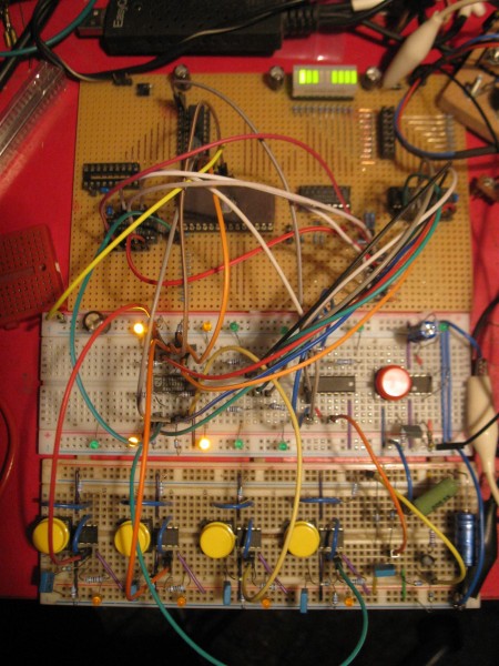
Currently I am actually using some breadboards and a part on perf. The perf part is a test board for EPROMs
I put together when I first started playng around with them and it saves me some wiring now. It has the EPROM,
the 8 latches and I am also using a 4040 divider on there to simulate neighbouring cells.
Recently I have also been designing some more double sided PCB's (even one with SMDs, I must be going madder)
as they can be more dense and are therefor smaller. If I need a couple it's actually cheaper than perf.
GoL 4 CELL EPROM testing.jpg
Description:
note: the shabby looking breadboard at the bottom spend many years in my kitchen with a ciruit on it.
Filesize:
367.71 KB
Viewed:
116 Time(s)
This image has been reduced to fit the page. Click on it to enlarge.
Joined: Jan 14, 2010 Posts: 5603 Location: Moon Base
Audio files: 705
Posted: Tue Jul 14, 2020 10:05 am Post subject:
Blue Hell wrote:
hmm .. with connectors it will be tricky too.
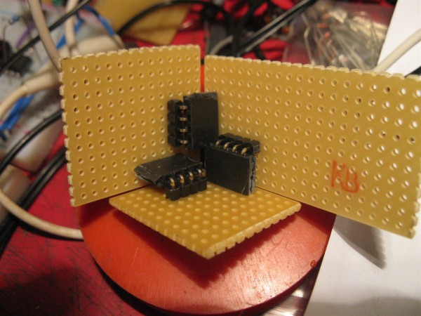
yeah, ehm,.. I didn't really think this through
I did manage to get them together after soldering, but only by bending things a bit. (I saw that going differently in my mind)
Not a big problem though I just have to decide which connectors (male/female) I use for what board. So I can't just make all
of them the same and then connect it together.
GOL 4 CELL EPROM - cubeconn test.jpg
Description:
Filesize:
281.66 KB
Viewed:
109 Time(s)
This image has been reduced to fit the page. Click on it to enlarge.
So I can't just make all
of them the same and then connect it together.
Maybe you could.. by using pin headers everywhere and then a sex changer inbetween .. female to femal that is .. I think I've seen such things as break-off strips too.
But the other way around is possible too .. females on the boards, and male to male inbetween, might be cheaper ... _________________ Jan
also .. could someone please turn down the thermostat a bit.
anyway .. that's a double dick one .. didnt really see any double cunts .. you could solder gender force bend 'm together I guess .. soldering up their male ends .. but ugly enough to just use wires instead I guess.
We used to have plenty of that stuff in the old company ... too bad they didn't end up at your place. _________________ Jan
also .. could someone please turn down the thermostat a bit.
Saw some amazon things show up too, but didnt look into those, maybe I would have when bozos would behave .. oh well.
And yeah, did it at times too, was always ugly .. but in my case it was for testing only .. so that was ok .. as long as it would connect for a while
pwew .. my freezer is not really in a hurry .. am making ice cream .. but still needs to be stirred from time to time .. freezing for 6 hours already. _________________ Jan
also .. could someone please turn down the thermostat a bit.
Joined: Jan 14, 2010 Posts: 5603 Location: Moon Base
Audio files: 705
Posted: Wed Jul 15, 2020 2:56 am Post subject:
ribbon cable wouldn't work as it also needs a to be mechanical connection, especially for a cube shape. I mean I don't want a floppy cube.
That picture does show something I still have to look for; low profile angled connectors, which oddly enough aren't the standard.
I did find them at TME and they might have some gender benders as well but I try to avoid ordering from there unless I really have to.
Will look a bit further once I am back from work, but I also need to figure out how many pins I actually need. I did make a start at the PCB design btw. _________________ "My perf, it's full of holes!" http://phobos.000space.com/ SoundCloudBandCampMixCloudStickney SynthyardsCaptain ColliderTwitchYouTube
IF you are using an Arduino, you can get away with 4 wires: 2 for power, a clock and a data wire to be fed to the infamous 74hc595 on each board and use them in chain mode. _________________ my synth
Joined: Jan 14, 2010 Posts: 5603 Location: Moon Base
Audio files: 705
Posted: Wed Jul 15, 2020 6:18 am Post subject:
Ah great so thats an option, thanks!
Grumble wrote:
IF you are using an Arduino, you can get away with 4 wires: 2 for power, a clock and a data wire to be fed to the infamous 74hc595 on each board and use them in chain mode.
You could emulate the serial communication with the 595 with the data from an eeprom
Per byte one clock signal and 7 data signals.... _________________ my synth
You cannot post new topics in this forum You cannot reply to topics in this forum You cannot edit your posts in this forum You cannot delete your posts in this forum You cannot vote in polls in this forum You cannot attach files in this forum You can download files in this forum

 Forum index » DIY Hardware and Software