| Author |
Message |
zipzap
Joined: Nov 22, 2005
Posts: 559
Location: germany
Audio files: 24
|
 Posted: Mon May 15, 2006 12:41 am Post subject:
State Variable Oscillator Posted: Mon May 15, 2006 12:41 am Post subject:
State Variable Oscillator |
  |
|
Hi! I built this State Variable Filter from Music from outer space,
http://www.musicfromouterspace.com/analogsynth/statevariablefilter.html
I was happy because it worked right away!. A happy accident happened when i tried to run it with no q-pot connection at the input. It became a vco ranging from below to above audio range. Didn´t expect that. with my moogladder things are different. No feedback connection= no resonance. Here it seems to be the other way around.
Well, i guess comparing the ladder to the state variable is like comparing wood to plastic. Can use both to build a chair, but in the inside they look different...
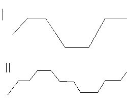
Anyway, the waveform looks something like a clipped triangle, shown in I.
During testing, the waveform somehow changed (i didn´t do anything) to what is drawn and labeled II.
I then started experimenting with different q input resistors. with about 5-10M you can use the q-pot to adjust the wave to become a clean sinewave. But this only works over a small range. If i setup a sinewave in one range, i may be able to play in one or two octaves, but lowering the pich further makes the sineamplitude become smaller till it vanishes. At higher pitch it gets louder till it comes to a clipping rest at the waveform drawn. The clipped wave has stable amplitude over the full range, becoming more like a square the higher we go.
Do you think it´s possible to somehow stabilize that behavior? get a stable sine over the whole range without readjusting feedback? Or even make it possible to blend from sine to the clipped wave with the q-pot?
WOuld be nice! The filter is easy to build and all that would be needed to turn it into a good vco would be mashed transistors and a tempco.
| Description: |
|
| Filesize: |
3.67 KB |
| Viewed: |
12710 Time(s) |
|
|
|
|
Back to top
|
|
 |
Uncle Krunkus
Moderator

Joined: Jul 11, 2005
Posts: 4761
Location: Sydney, Australia
Audio files: 52
G2 patch files: 1
|
| Posted: Mon May 15, 2006 6:34 am Post subject:
|
|
|
I gotta get some of them "mashed transistors"  
_________________
What makes a space ours, is what we put there, and what we do there. |
|
|
Back to top
|
|
|
zipzap
Joined: Nov 22, 2005
Posts: 559
Location: germany
Audio files: 24
|
| Posted: Mon May 15, 2006 7:46 am Post subject:
|
|
|
| with chickenheads? |
|
|
Back to top
|
|
|
toppobrillo

Joined: Dec 10, 2005
Posts: 766
Location: oakland, ca
G2 patch files: 1
|
| Posted: Mon May 15, 2006 6:07 pm Post subject:
|
|
|
this type of oscillation happening is not amplitude stable thru a sweep [unless the output is saturated of course] it would be easier to tame the saturation then boost the sines amplitude at low frequencies. once again, diodes to the rescue!
in fact, you could use a simpler version of the sine shaper circuit i posted there to do it. when the diodes in the neg. feedback loop are forward biased, they conduct and make the total feedback resistance less, lowering the gain.
maybe look at the ms-20 vcf regen section. a self oscillating filter is nice but no replacement for the range and stability of the type of VCO as implemented on rays site and elsewhere. at it's core, it is pretty danged simple too.
-it's all the waveshaping circuitry that complicates it. if you want a good sine wave VCO with an option to clip like that, build a tri-core VCO and shape the TRI, then build perhaps a VC clipper- i have a circuit for that too. it's cool, if you remove one resistor, it becomes a 'dead zone' circuit.
josh |
|
|
Back to top
|
|
|
zipzap
Joined: Nov 22, 2005
Posts: 559
Location: germany
Audio files: 24
|
| Posted: Tue May 16, 2006 1:24 am Post subject:
|
|
|
| Quote: | at it's core, it is pretty danged simple too.
|
Hi Josh, your right with that for sure! I made a pcb for Rays vco, still need to get the temco, but i know that that is a real vco designed for the purpose.
This filter is not. on the other hand, you can´t have enough vcos and with mashed transistors and a tempco this could be as stable i guess. Even if it isn´t it could be a FM or sync source or be played by my sequencer. Or make a drum or FX osc. As i noticed the oscillation i knew if there is another osc just one swich away then i wanna have that swich.
The main purpose of this circuit is filtering of course.
Again, what suprised me (i´m propably easily suprised) is that the q controll works opposite to the way in my moog ladder. Less feedback = more q.
| Quote: | in fact, you could use a simpler version of the sine shaper circuit i posted there to do it. when the diodes in the neg. feedback loop are forward biased, they conduct and make the total feedback resistance less, lowering the gain.
|
You meen put the sineshaper in the filters feedback loop? Or in the feedback loop of the opamp in the sineshaper, than place the shaper to the filters output? |
|
|
Back to top
|
|
|
ian-s

Joined: Apr 01, 2004
Posts: 2669
Location: Auckland, New Zealand
Audio files: 42
G2 patch files: 626
|
| Posted: Tue May 16, 2006 3:57 am Post subject:
|
|
|
If you can get a wide range, stable sine out of it. Then another plus is that you get free quadrature sine from one of the other outputs.
Hook both to a VC crossfader modulated by an audio rate sine, and you have DX7 style tones (with limited modulation index but still very useful). |
|
|
Back to top
|
|
|
zipzap
Joined: Nov 22, 2005
Posts: 559
Location: germany
Audio files: 24
|
| Posted: Tue May 16, 2006 5:13 am Post subject:
|
|
|
cool! I think maybe some kind of filtering in the feedback loop could do it. No idea how exactly that could be done though.
A vc-crossfader is basically two linear vcas with cv offset at the center of the cv range, right? so feeding a cv into one vca and the inverted cv into the other will do the crossfading. Never tried it, but dx7 sounds fun. |
|
|
Back to top
|
|
|
toppobrillo
Joined: Dec 10, 2005
Posts: 766
Location: oakland, ca
G2 patch files: 1
|
| Posted: Tue May 16, 2006 7:07 pm Post subject:
|
|
|
yeah you would put it in series with the fedback signal. wouldnt you get
120 deg phase dif, not 90?
josh |
|
|
Back to top
|
|
|
zipzap
Joined: Nov 22, 2005
Posts: 559
Location: germany
Audio files: 24
|
| Posted: Wed May 17, 2006 1:54 am Post subject:
|
|
|
I thought thats 180 deg. Well i don´t know. I´ll try it. What would be a simplified version? Might as well build the whole thing.
Some filtering in the feedback might also work, but again, no idea. I guess it would be like a slope eq, lowering the low freq in the feedback so in the end they get louder. would have to do some maths i cant do though. |
|
|
Back to top
|
|
|
ian-s
Joined: Apr 01, 2004
Posts: 2669
Location: Auckland, New Zealand
Audio files: 42
G2 patch files: 626
|
| Posted: Wed May 17, 2006 3:05 am Post subject:
|
|
|
| AFAIK the LP,BP,HP outputs are 0,90,180 degrees. |
|
|
Back to top
|
|
|
zipzap
Joined: Nov 22, 2005
Posts: 559
Location: germany
Audio files: 24
|
| Posted: Wed May 17, 2006 3:48 pm Post subject:
|
|
|
Ok, here´s what i did, just for a try: Two antiparallel Diodes in the feedbackloop, no aditional resistor. Perfect Sine over the whole range, going beond audio in both directions, with no more clipping (which i´ll propably apply to it later - again). From the highest pitch i can hear to the lowest it´s about 5-10% difference in amplitude. That´s nothing compared to what it was!
I was using silicon diodes, maybe germanium or the "ideal diode" will work even better (without them even knowing...)
Ok, there still are real vcos, but with this the VCF/VCO module is just one swich to go.
I´ll have to check if this´ll work with larger cabs for LFO mode, it only goes to about 5hz with the filter values. |
|
|
Back to top
|
|
|
toppobrillo
Joined: Dec 10, 2005
Posts: 766
Location: oakland, ca
G2 patch files: 1
|
| Posted: Wed May 17, 2006 4:03 pm Post subject:
|
|
|
| cool! awesome, im glad you got it going. |
|
|
Back to top
|
|
|
zipzap
Joined: Nov 22, 2005
Posts: 559
Location: germany
Audio files: 24
|
| Posted: Thu May 18, 2006 5:24 am Post subject:
|
|
|
Here are two soundexamples. A (manual, kind od shaky) sweep and a little sequence. The high notes get louder, but i think it´s still ok. Some eqing would probably help. Is it easy to build a small filter for the sine out? might be just an OPamp with some cs and rs. Would be needed for every out though, and then every out is needed twice, for filter and osc use. Not very economic.
If i invert the BP i should get 0, 90, 180, 270 deg, right? Still some confusion about that...
Would be cool to have a LFO Mode. I tried 10nf cabs, no oszillation. Don´t know why.
Whats also strange is that when i tried to use germanium diodes nothing happened. no oszillation, too.
Anyway, here´s what it sounds like. Looks not as sinish as through the scope at the filter out, but thats propably couse of it´s going through vca, tubepramp, mixingdesk, AD converter, MP3 conversion. Poor sine. Funny how the high freq sine looks after it´s been digitalized.
Edit: Removed the samples. Needed space. It works and we know what a sine sounds like.
_________________
http://www.myspace.com/lorolocoacousticpop
http://www.myspace.com/petrolvendor
music and transcribed jazz basslines
Last edited by zipzap on Fri Aug 11, 2006 7:51 am; edited 1 time in total |
|
|
Back to top
|
|
|
toppobrillo
Joined: Dec 10, 2005
Posts: 766
Location: oakland, ca
G2 patch files: 1
|
| Posted: Thu May 18, 2006 2:31 pm Post subject:
|
|
|
| good samples, good range on that, too. |
|
|
Back to top
|
|
|
zipzap
Joined: Nov 22, 2005
Posts: 559
Location: germany
Audio files: 24
|
| Posted: Fri May 19, 2006 8:08 am Post subject:
|
|
|
| Quote: | Then another plus is that you get free quadrature sine from one of the other outputs.
Hook both to a VC crossfader modulated by an audio rate sine, and you have DX7 style tones (with limited modulation index but still very useful). |
Wow, i just tried it in the g2 demo (first time i really used it, hooked up for two hours, they really give it away for free. thats awsome!).
This FM type of stuff is fun! Need to build two vcas quick now. |
|
|
Back to top
|
|
|
13"

Joined: May 20, 2006
Posts: 17
Location: sthlm sweden
|
| Posted: Sun May 21, 2006 4:49 am Post subject:
|
|
|
Cool!
I´m about to build the same filter,
and I definitely will add your mod to it!
-martin |
|
|
Back to top
|
|
|
zipzap
Joined: Nov 22, 2005
Posts: 559
Location: germany
Audio files: 24
|
| Posted: Mon May 22, 2006 12:04 pm Post subject:
|
|
|
Tell us how it worked for you when you get to it!
Here is another option i like even more right now: Instead of the silizium diodes i tried using two red leds. they produce even less feedback (=stronger oszillation). I can now use the res pot to controll the sine amplitude from about 2vpp till about 15 where it starts to clip and beyond. It´s very stable over the whole range.
Still don´t manage to find a LFO tweak, though. |
|
|
Back to top
|
|
|
zipzap
Joined: Nov 22, 2005
Posts: 559
Location: germany
Audio files: 24
|
| Posted: Tue May 23, 2006 2:46 pm Post subject:
|
|
|
| and don´t forget to fade some signal to the input while in osc-mode and see what happens. Lots of fun. |
|
|
Back to top
|
|
|
zipzap
Joined: Nov 22, 2005
Posts: 559
Location: germany
Audio files: 24
|
| Posted: Mon Jun 12, 2006 11:39 am Post subject:
|
|
|
| if anyone builds this mod and it doesn´t work it may be because of the cabs used. while experimenting with this i was using 560p styroflex. when finishing the filter i put in some normal ceramic 470p, and it didn´t work anymore. swiched back the old cabs and got my sine back. |
|
|
Back to top
|
|
|
|

 Forum index » DIY Hardware and Software
