| Author |
Message |
fluxmonkey
Joined: Jun 24, 2005
Posts: 708
Location: cleve
|
 Posted: Tue Sep 11, 2007 4:43 am Post subject: Posted: Tue Sep 11, 2007 4:43 am Post subject:
|
  |
|
| vtl5c3 wrote: | Finished my first iteration of this dual pattern generator. I replaced the simple diode inputs with the input comparator (X4) that Ken Stone designed for his Gated Comparator, since it's nice and flexible. This way I can clock each pattern generator off any input signal, not limited to pulses. The comparator has additional offset inputs, so you can create quite complex timing variations if you voltages going into all eight inputs.
[Edit]
Am adding my PCB layout. This has been tested. Includes the comparator (x2) as found here: http://www.cgs.synth.net/modules/cgs13_gated_comparator.html In the schematic, it's the circuit at the top left that connects to pin 7 of the CD4015 |
vtl...
thanks for posting the PCB... any chance you could add a schemo? i'm not 100% sure i'm following all your modifications, but i'm sure a circuit diagram would clear it all up... a pictures worth 1039.7 words (approx.)...
bbob |
|
|
Back to top
|
|
 |
Rykhaard
Joined: Sep 02, 2007
Posts: 1290
Location: Canada
|
| Posted: Tue Sep 11, 2007 7:10 am Post subject:
|
|
|
| bugbrand wrote: | Hey, sorry I didn't get a chance to chip in before but I'm damn excited to hear about how people run with these ideas. And nice nice work VTL for posting the pcb! Hooray!
|
Much appreciation to VTL as well, for posting that layout! It saved my having to spend the extra time to figure it out myself, as well.  Appreciation also for inclusion of the Comparator section from another of Ken Stone's modules. Appreciation also for inclusion of the Comparator section from another of Ken Stone's modules.
| Quote: |
I gotta say that some of my design came down to thinking about how big I wanted the module to be and, therefore, how many panel controls I could use... hehe! And I tried to make it all quickly rather than thinking about all the possibilites. Designers, eh?! Some of the ideas used on the Klee may actually be quite interesting too...
Ah well.... looking forward to hearing and seeing your developments.
Good luck! |
 Based on my own past experiences - a note of warning to others out there, that do your own PCB layouts / designs, has just been typed below Based on my own past experiences - a note of warning to others out there, that do your own PCB layouts / designs, has just been typed below
Oddly enough - whilst falling asleep last night, watching ultra-chef Gordon Ramsay's show "Kitchen Nightmares" and marvelling again at his example of how many restaurants approach failure by going for things that are TOO fancy - and how most of those that he helps out, by bringing them back to SIMPLE dishes and fair made me realize, BIG TIME:
In my building past - panels / modules that I have had fail, were usually overboard in extra features and complexities. Here in the past couple of days, I've been adding feature after feature, to a new panel, in design.
With the amount of work that goes into a multiple module panel (as I'm restricted to, by using wooden panels) - the more complex that I make it, the greater my chances are, of having failures.
Whilst I'm still in the process of laying out all of the module's circuitry traces / etc. on the PCB, I'm going to wander back to the Design section of my webpage and think it all out in typing - to come to a simpler solution, to try and steer myself away from potential failure.
(edit) The Design section of my webpage has the overall plan updated. Off to finishing the PCB.  |
|
|
Back to top
|
|
|
moosapotamus

Joined: May 11, 2007
Posts: 113
Location: New Hampshire USA
|
| Posted: Tue Sep 11, 2007 1:36 pm Post subject:
|
|
|
| Rykhaard wrote: | | In my building past - panels / modules that I have had fail, were usually overboard in extra features and complexities. |
I can relate to that... The enemy of 'good' is 'better'.
~ Charlie
_________________
moosapotamus.net
"I tend to like anything that I think sounds good" |
|
|
Back to top
|
|
|
andrewF

Joined: Dec 29, 2006
Posts: 1176
Location: australia
Audio files: 4
|
| Posted: Wed Sep 12, 2007 1:57 am Post subject:
|
|
|
made this one today - original bugbrand version! Thanks for sharing!
it is a lovely(  ) design = a lot of fun for little effort or expense. ) design = a lot of fun for little effort or expense.
i will be making a few more of these.
i can see the advantages of comparators on the inputs and perhaps glide on the output, but i've already got plenty of logic modules, CV processors and whatall, so no need for me. |
|
|
Back to top
|
|
|
bugbrand

Joined: Nov 27, 2005
Posts: 846
Location: Bristol, UK
Audio files: 1
G2 patch files: 1
|
|
|
Back to top
|
|
|
andrewF
Joined: Dec 29, 2006
Posts: 1176
Location: australia
Audio files: 4
|
| Posted: Fri Sep 14, 2007 12:26 am Post subject:
|
|
|
| bugbrand wrote: | | Andrew --- freaking ace! Show us a pic! And mp3s?! |
guess you'd rather see a panel but I'm about 15 modules behind with panel building - nevertheless here's the circuit.

this is such a good design for new DIYers or small systems. easy to build and a lot of fun sounds to make. again, Thanks Bugbrand!  |
|
|
Back to top
|
|
|
Rykhaard
Joined: Sep 02, 2007
Posts: 1290
Location: Canada
|
| Posted: Fri Sep 14, 2007 10:43 am Post subject:
|
|
|
I was finally after working on it all week, hoping to have my 1st of 2 Pattern Generators up and running for testing today. (With the Ken Stone / vtl comparator addition and my NAND Gates input addition / replacement).
This time - I thought "Let's shoot on video, the 1st power on - just in case it blows up!"
Sure enough - the 22R protection resistor on my +V power input, let out the Magic Smoke. Uh oh. Even though I had tested for power supply shorts first, something's wrong. Time to go and bug solve. I'll be posting the nararrated video at my website, tomorrow morning - for anyone interested.
Minor update: 30 min. later: Ground to the CD4052 was not soldered; center connection to 2nd Comparator's Voltage amount pot, not soldered.
Powered up - Comparator #1 / NAND Gate # 1 - working beautifully.
Hooked up first cable to Comp. #2 and Magic Smoke came out of the new +V input resistor. Bug solving tomorrow. Off to work.
Impressed SO far with #1 working though! |
|
|
Back to top
|
|
|
Rykhaard
Joined: Sep 02, 2007
Posts: 1290
Location: Canada
|
| Posted: Sat Sep 15, 2007 10:08 am Post subject:
|
|
|
Ok! I THINK I have found the solution as to WHY my 1st of 2 Pattern Generators has released Magic Smoke, twice!
Now - I am still lacking on theory a fair bit. My biggest trouble is not having yet found, an explanation to the Kirschoff Law (of resistance?) that I can wrap around my head. I understand most other theory BASICs though, in my self-taught electronics knowledge.
I've posted my analysis of the problem in the Design section of my modular synth's webpage. http://deathlehem.com/wsb4569662402/design.html
Could those of you, with far more knowledge than I - tell me whether my realization / find that I typed about, is correct? I'm just about to do the (hopeful) fix now and see whether the Pattern Generator works, as it should.
The video that I shot yesterday of the first Magic Smoke release, is also up there for any that would like to watch it. Not that exciting, but I'll be videoing every first power up for a new module, from now on, for my own history purposes.
Thank you greatly for any help!! I'm still learning. 
(edit) 1:42pm - Oooooo. Sorry about that! I had NOT posted my webpage edit, WITH my analysis until NOW - with my Magic Smoke #3 addition to it. Duh on my part.
(edit) 6:50pm Sunday. 98% of Pattern Generator #1 (with Ken Scott Comparator) is working. Odd trouble that I may find out tomorrow, but it IS working. I'll have video up on my site and/or here, once I get at least the 2nd one up and running. |
|
|
Back to top
|
|
|
Rykhaard
Joined: Sep 02, 2007
Posts: 1290
Location: Canada
|
| Posted: Tue Sep 18, 2007 10:10 am Post subject:
|
|
|
Wednesday - Ooops. Sorry for posting the request below this, yesterday. I've found my PCB error, causing the 350+ milliamp current draw into my board with the 2 Pattern Generators. That problem, after 6 days is finally solved.
-----
Tuesday -
I've just started testing my 2nd one - Magic Smoke again - and measuring the current draw, I'm looking at (get this) 375 milliamps of current draw on my meter! (Over 5 watts of power, through a 1/4 watt resistor. No wonder it cooks. )
Thanks for any help. |
|
|
Back to top
|
|
|
Rykhaard
Joined: Sep 02, 2007
Posts: 1290
Location: Canada
|
Posted: Fri Sep 21, 2007 10:57 am Post subject:
 Video of my 2 Pattern Generator's is up at my site! Video of my 2 Pattern Generator's is up at my site! |
|
|
I've just posted a short 1 minute video in the Design section at my website showing the 1st of 2 x Divide By 7 Counters (with an LED and Output for each of it's 7 bits), driving both the comparators of each of my 2 x BugBrand Pattern Generators.
15 LEDs happily blinking away!
It's a simple test of all 3 modules with simple audio as well.
To finish this panel, I have yet to attach everything for:
- the 2nd Divide By 7 Counter with Outputs and LEDs
- 3 Clocks (each driving 1 colour of a tri-colour LED)
- 1 x 3 input non-inverting Summer with built in Slew, for softening the edges of anything input into it.
Once the next 5 modules are completed, I'll then take the panel apart, stain and polyurethane it and it'll be completed.
Many MANY thanks to Tom Bugs for his Pattern Generator and vtl3 for his Comparator addition to it! Tons of wonderful audio hell and audio beauty shall in part be created with these 2 little buggers. |
|
|
Back to top
|
|
|
drapdap

Joined: Oct 11, 2004
Posts: 204
Location: London
Audio files: 1
G2 patch files: 1
|
| Posted: Sat Sep 22, 2007 6:13 am Post subject:
very Bead |
|
|
hello
excuse both my english and my ignorance!
theres something called "Bead" on vtl5c3's layout. its just a piece of wire, connecting the to holes, right?
robert |
|
|
Back to top
|
|
|
Rykhaard
Joined: Sep 02, 2007
Posts: 1290
Location: Canada
|
| Posted: Sat Sep 22, 2007 6:34 am Post subject:
|
|
|
The bead on vtl's layout is either a Ferrite bead; 10 to 22 ohm resistor or a piece of wire.
I myself have been using a 22 ohm resistor for +V and -V power supply inputs for about 18 months now. They have saved me from blowing MANY fuses, in that time. |
|
|
Back to top
|
|
|
drapdap
Joined: Oct 11, 2004
Posts: 204
Location: London
Audio files: 1
G2 patch files: 1
|
| Posted: Sat Sep 22, 2007 7:07 am Post subject:
|
|
|
ah, ok, thanks a lot!
i just did not know the term "bead" - my bad.
just etched a pcb (i still work in acid), soldiering the resistors now.
somehow this smells like a classic.
robert |
|
|
Back to top
|
|
|
Rykhaard
Joined: Sep 02, 2007
Posts: 1290
Location: Canada
|
| Posted: Sat Sep 22, 2007 7:12 am Post subject:
|
|
|
Heh. MY bad, was not having thought of it before and all of the fuses that I'd blown before I'd added them to every single module.
I was so impressed by the video from Tom Bugs' 1st one, I had to build 2. Very very glad that I did!!
Now I'm pondering doing a 1V/octave modification to one of them. lol |
|
|
Back to top
|
|
|
drapdap
Joined: Oct 11, 2004
Posts: 204
Location: London
Audio files: 1
G2 patch files: 1
|
| Posted: Sat Sep 22, 2007 7:36 am Post subject:
|
|
|
yes, i saw that too, it bit me, and it was something i really needed anyways,
thanks for all of you guys here, it's wonderful stuff!
also put a twins down into the acid, luckily my modular is way out of the standard
european size (doepfer that is, is eurorack the name?) i hope everything will fit somehow.
took a peak of Damian, so terrific, congrats! 
robert |
|
|
Back to top
|
|
|
Scott Stites
Janitor


Joined: Dec 23, 2005
Posts: 4127
Location: Mount Hope, KS USA
Audio files: 96
|
| Posted: Sat Sep 22, 2007 8:55 am Post subject:
|
|
|
Being on dial-up, I haven't had a chance to listen to the Seq-y samples yet on YouTube. Where I'm not on dial-up, YouTube is blocked by a certain firewall.
However, the firewall doesn't mind WMA's
So I was able to check out this flick of DAMIAN in action:
| Quote: | | Though not very many people are into Noise Genres, I do have a video of myself working with the 4 axii controller only, controlling 3 VCOs and VCF Cutoff as well as LFO amounts - up in the My Tunes section of my personal webpage: http://www.rykhaard.com/mytunes.html |
That quote is from this thread:
http://www.electro-music.com/forum/topic-20394.html
It's pretty good stuff - I *really* like what begins right around the 8 minute mark or so (IIRC).
Cheers,
Scott
_________________
My Site |
|
|
Back to top
|
|
|
Rykhaard
Joined: Sep 02, 2007
Posts: 1290
Location: Canada
|
| Posted: Sat Sep 22, 2007 2:14 pm Post subject:
|
|
|
| Scott Stites wrote: | Being on dial-up, I haven't had a chance to listen to the Seq-y samples yet on YouTube. Where I'm not on dial-up, YouTube is blocked by a certain firewall.
However, the firewall doesn't mind WMA's
So I was able to check out this flick of DAMIAN in action:
|
I just use XP's Movie Maker to convert videos from my cameras to it's stock mode. Seeing as how you're able to play IT, I'll continue to stick with it! 
| Quote: |
| Quote: | | Though not very many people are into Noise Genres, I do have a video of myself working with the 4 axii controller only, controlling 3 VCOs and VCF Cutoff as well as LFO amounts - up in the My Tunes section of my personal webpage: http://www.rykhaard.com/mytunes.html |
That quote is from this thread:
http://www.electro-music.com/forum/topic-20394.html
It's pretty good stuff - I *really* like what begins right around the 8 minute mark or so (IIRC).
Cheers,
Scott |
Thankee very much Scott! Rarely hear anything on a Noise tune and rarer still, any sort of compliment!
Now I just guesstimated the positiion of the 8 minute mark. (Just past 1/2 way through the 14 minutes of it). Was that the HIGH resonance percussion part, with more resonance after it?
If so - that was me manually tapping the control surface of the Korg Kaoss Pad on it's Filter w/ Feedback setting.
More noise video's'll be coming soon, after I complete my current panel, I'm building.  Possibly Atmospheric as well, sometime after. Possibly Atmospheric as well, sometime after. |
|
|
Back to top
|
|
|
Rykhaard
Joined: Sep 02, 2007
Posts: 1290
Location: Canada
|
| Posted: Wed Sep 26, 2007 7:17 am Post subject:
A new Pattern Generator video posted |
|
|
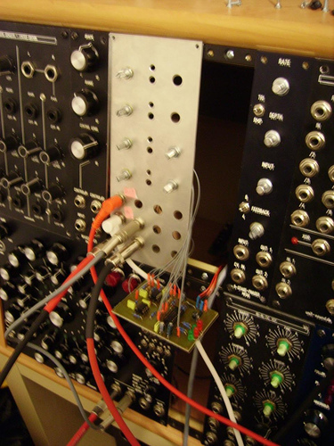
I shot a new video on Tuesday after finishing the hookup of my 3 x Clocks and Slewing Summer in my current panel. It's about 6 1/2 minutes long and nararrated throughout - hopefully coming across with a decent idea as to what I'm doing with the modules in the panel.
The modules are only controlling an unneffected single VCO, to get the idea across. The power potential from Tom Bugs' Pattern Generator combined with the power of Ken Stone's Master Divider and other modules - is almost overwhelming.
Here's a pic from the beginning of the video, as well as a direct link to it.

The modules used in the video include:
- 2 x Pattern Generators
- 1 x Divide By 7 Divider
- 2 x Clocks
I HIGHLY recommend building Ken Stone's Master Divider. With the original one I'd built in 2006, I hooked 3 of it's bits up to drum sounds, to use it as a simple drum machine.
The http://deathlehem.com/wsb4569662402/design.html - 6 1/2 minute video. Enjoy. |
|
|
Back to top
|
|
|
bugbrand
Joined: Nov 27, 2005
Posts: 846
Location: Bristol, UK
Audio files: 1
G2 patch files: 1
|
| Posted: Thu Sep 27, 2007 9:52 am Post subject:
|
|
|
Hey Ryk nice work and your video made me smile - and laugh a few times:: 'hope you don't mind me smoking' 'come on change' 'oops hooked up the wrong output' hehe! Yeah rocking approach.
I'm thinking that your divider is more like a 2/4/8/16/32/64/128 than divide by 7, right? Certainly looks like that anyways & i could see why you'd maybe call this a divide by 7. Yeah, its def. a good module to have but I reckon you'll get even more excited by Ken's Pulse Divider which does do the 2/3/4/5/6/7/8 divisions -- I freaking love this because it gets you out of the straight'n'standard 16 length rhythms and gets all sorts of seemingly ever-evolving patterns generated when you make use of the 3/5/7s - mmm polyrhythms!
_________________
http://www.bugbrand.co.uk
http://www.bugbrand.blogspot.com |
|
|
Back to top
|
|
|
Rykhaard
Joined: Sep 02, 2007
Posts: 1290
Location: Canada
|
| Posted: Thu Sep 27, 2007 9:12 pm Post subject:
|
|
|
| bugbrand wrote: | Hey Ryk nice work and your video made me smile - and laugh a few times:: 'hope you don't mind me smoking' 'come on change' 'oops hooked up the wrong output' hehe! Yeah rocking approach.
|
Haha! I were just being me! Thank you very muchlee as well! And thank YOU for coming UP with the Pattern Generator! I'm just ACHING to do a 1V/oct. mod. for it, as well!
| Quote: |
I'm thinking that your divider is more like a 2/4/8/16/32/64/128 than divide by 7, right? Certainly looks like that anyways & i could see why you'd maybe call this a divide by 7.
|
True. When I had built the 1st one, with my 1st 1V/oct. sequencer attempt, I immediately saw how useful it is for doing things at different timings, as well as combining outputs through NAND Gates for different functions. With a sequencer, it's hugely useful as well. (More on that below).
I actually DON'T have a permanent name for it yet. I sorta stuck with Ken's Divider portion from his Master Divider.
| Quote: |
Yeah, its def. a good module to have but I reckon you'll get even more excited by Ken's Pulse Divider which does do the 2/3/4/5/6/7/8 divisions -- I freaking love this because it gets you out of the straight'n'standard 16 length rhythms and gets all sorts of seemingly ever-evolving patterns generated when you make use of the 3/5/7s - mmm polyrhythms! |
Wha'??? That module DOES work that way????? I've been wanting to do Frank Zappa'ish polyrhythms for YEARS! I'm going to have to go and look at his schematic. If it's easy, I'll just lay it out myself. If not, I'll order one. Thank you greatly for that tip!
The 2nd Divider will be finished tomorrow morning. If it's bug free, I hope to set up a simple hook up with a drum pattern and 1 Patt.Gen. playing a 'bassline', whilst the other noodles away. Once done - I'll shoot a video of it as well.
1V/Oct. Sequencer and Drum Sequencer plans are just about pouring out of my mind. I hope to start prototyping this weekend, if possible. Once I have something working, I'll be posting all of it to my webpage as well, for any others that may be interested. |
|
|
Back to top
|
|
|
RF

Joined: Mar 23, 2007
Posts: 1502
Location: Northern Minnesota, USA
Audio files: 28
|
|
|
Back to top
|
|
|
janvanvolt

Joined: Nov 24, 2005
Posts: 285
Location: Mainz, Germany
|
| Posted: Mon Oct 15, 2007 6:32 pm Post subject:
|
|
|
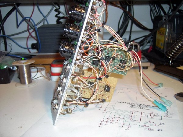
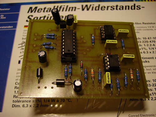
So here i am, also finished my (preliminary) bug pattern generator. After exchanging the CD4052 (which was D.O.A) the unit works as expected.
Some photos for your enjoyment ... off now to design the frontpanel for this thingie.
| Description: |
|
| Filesize: |
131.88 KB |
| Viewed: |
7251 Time(s) |
|
| Description: |
|
| Filesize: |
129.81 KB |
| Viewed: |
7252 Time(s) |
|
|
|
|
Back to top
|
|
|
julianw

Joined: Jul 30, 2007
Posts: 78
Location: UK
|
| Posted: Mon Oct 29, 2007 8:49 am Post subject:
Re: My first modification idea |
|
|
I just populated a dual version of the PCB posted here by vtl, slightly modded pcb below, its just two pcbs stuck together with common power for both.
How would I change the design for NAND and NOR functionality?
| Rykhaard wrote: | After a few hours of thought on modifications for the pattern generator of yours, I just came up with this idea:
Seeing that you've built a wonderful dual unit, with both of them controlled by the same 2 logic inputs, I'm going to build a dual unit as well, with this change though:
Patt.Gen. #1's 4 outputs will be controlled by the 2 NOR inputs:
1 = 0 _ 2 = 0 _ Out = 0 (Output the 1st input)
1 = 0 _ 2 = 1 _ Out = 1 (Output the 2nd input)
1 = 1 _ 2 = 0 _ Out = 1 (Output the 3rd input)
1 = 1 _ 2 = 1 _ Out = 1 (Output the 4th input)
Patt.Gen #2's 4 output will be controlled by the 2 NAND inputs:
1 = 0 _ 2 = 0 _ Out = 1 (Output the 4th input)
1 = 0 _ 2 = 1 _ Out = 0 (Output the 3rd input)
1 = 1 _ 2 = 0 _ Out = 0 (Output the 2nd input)
1 = 1 _ 2 = 1 _ Out = 0 (Output the 1st input)
Having the 2 Patt.Gen.'s opposing each other, in which output is selected would allow you to:
- send different CVs to VCAs for stereo control of audio
- send different CVs to VCAs for ampitude control of audio to change a sound depending on which inputs are HIGH
- many other possibilities
Taking this a step further - go with a CD4051 giving you 3 bits of control, over which of 8 inputs for each of 2 x CD4051's are sent to their respective outputs.
Time to start laying out a circuit for this on copper. (Of course, I'll be adding the other's recommendations of input buffering for the control bits.)
Again - a wonderful module idea from you, Bug!
(edit) P.S. Oh yeah! I just remembered another addition to it: Portamento for each of the outputs. |
| Description: |
|
| Filesize: |
39.19 KB |
| Viewed: |
120 Time(s) |
| This image has been reduced to fit the page. Click on it to enlarge. |
|
|
|
|
Back to top
|
|
|
vtl5c3
Joined: Sep 08, 2006
Posts: 425
Location: PDX
Audio files: 13
|
| Posted: Mon Oct 29, 2007 9:13 am Post subject:
|
|
|
| I think for NOR functionality, you'd simply need to add an inverter to one of the clock inputs, since they're already doing the OR thing. Not sure about the AND thing. I'm guessing there's a few different ways to do it. |
|
|
Back to top
|
|
|
RF
Joined: Mar 23, 2007
Posts: 1502
Location: Northern Minnesota, USA
Audio files: 28
|
| Posted: Mon Oct 29, 2007 9:31 am Post subject:
|
|
|
Man - That pcb looks clean compared to my perfboard version - nice job.
A quick update on mine - after playing with it a bit, I pulled the "OR" input and added Ken Stone's Gate to Trigger converter to each side of the module. I think it's a nice addition and I already have a module elsewhere in my system to do OR's, NOR's and AND's and NAND's.
Bruce |
|
|
Back to top
|
|
|
|

 Forum index » DIY Hardware and Software