| Author |
Message |
yusynth

Joined: Nov 24, 2005
Posts: 1314
Location: France
|
 Posted: Sun Jun 17, 2007 2:11 am Post subject:
yusynth Sawanimator Posted: Sun Jun 17, 2007 2:11 am Post subject:
yusynth Sawanimator |
  |
|
Hi all
Just an announcement of an important update of the YUSYNTH SAWANIMATOR module. I designed a new PCB which introduces a small improvement, this does not change any part and the component layout keeps the same. However the wiring diagram is now different from the previous version.
Have fun 
Yves - yusynth
_________________
Yves |
|
|
Back to top
|
|
 |
tomcat
Joined: Oct 14, 2005
Posts: 141
Location: earth
|
| Posted: Sun Jun 17, 2007 5:41 pm Post subject:
|
|
|
You have a description of the changes?
Or still the old infos online. I have already 2 pcbs laying around but unfortunately i didnt save the old page. |
|
|
Back to top
|
|
|
yusynth
Joined: Nov 24, 2005
Posts: 1314
Location: France
|
| Posted: Sun Jun 17, 2007 11:05 pm Post subject:
|
|
|
Hi
The change is minor, it concerns the output connetor (2 pins), on the old pcb, only one pin (the one facing the center of the PCB) was actually connected (to the output 1K resistor), the second pin (the one facing the PCB edge) was free. On the new board the pins have been swapped and both are now connected : the one facing the PCB edge is now the actual output pin (connected to 1K resistor) and the second pin is now connected to the PCB ground.
If my explaination are not crystal clear don't hesitate to mail me I will send you the wiring diagram for the old PCB.
Cheers
_________________
Yves
Last edited by yusynth on Wed Jun 20, 2007 10:54 pm; edited 1 time in total |
|
|
Back to top
|
|
|
tomcat
Joined: Oct 14, 2005
Posts: 141
Location: earth
|
| Posted: Wed Jun 20, 2007 5:00 pm Post subject:
|
|
|
| Thanks, without the PCB in the hand your explanation sounds crystal clear like perrier |
|
|
Back to top
|
|
|
Appliancide*

Joined: Jul 04, 2007
Posts: 126
Location: Paul lives in a 1920’s film
|
| Posted: Wed Dec 03, 2008 5:24 pm Post subject:
|
|
|
Is ok to use 200k trimmers instead of the 220k ones? And for the 1uf caps is it ok to use electolytic? If so, which way should they be mounted?
Thanks and sorry if these questions have been asked before.
Paul
_________________
http://appliancide/blogspot.com |
|
|
Back to top
|
|
|
yusynth
Joined: Nov 24, 2005
Posts: 1314
Location: France
|
| Posted: Thu Dec 04, 2008 3:26 am Post subject:
|
|
|
| *Appliancide* wrote: | Is ok to use 200k trimmers instead of the 220k ones? And for the 1uf caps is it ok to use electolytic? If so, which way should they be mounted?
Thanks and sorry if these questions have been asked before.
Paul |
200K should be OK.
Do not use a polarised capacitor for this, or if you cannot avoid this then use two 2.2uF mounted in series with opposite polarisation.
_________________
Yves |
|
|
Back to top
|
|
|
etaoin

Joined: Jun 30, 2005
Posts: 761
Location: Utrecht, NL
|
| Posted: Thu Dec 11, 2008 8:57 am Post subject:
|
|
|
| yusson wrote: | | if you cannot avoid this then use two 2.2uF mounted in series with opposite polarisation. |
That will give you 1.1uF capacitance wouldn't it?
By the way, I had the Cynthia Saw animator here for a couple of days and that sounded quite different. As you both started from Hutchins' design, any idea what can make it different? Just from listening to it I'd say the Cynthia one uses higher modulation frequencies and lower modulation depth, but I can't be sure.
_________________
http://www.casia.org/modular/ |
|
|
Back to top
|
|
|
yusynth
Joined: Nov 24, 2005
Posts: 1314
Location: France
|
| Posted: Thu Dec 11, 2008 10:58 am Post subject:
|
|
|
| Etaoin wrote: |
That will give you 1.1uF capacitance wouldn't it? |
Yes exactly
| Etaoin wrote: | | By the way, I had the Cynthia Saw animator here for a couple of days and that sounded quite different. As you both started from Hutchins' design, any idea what can make it different? Just from listening to it I'd say the Cynthia one uses higher modulation frequencies and lower modulation depth, but I can't be sure. |
Yes this is quite normal because I integrated only two parallel stages while in Cynthia's there are six stages and it also includes a mixer.
I settled for two because I felt this was sufficient if using a wider modulation index. I did not include a mixer because I wanted this module to be also used for other purposes such as phase shifted modulation of other modules.
_________________
Yves |
|
|
Back to top
|
|
|
Funky40
Joined: Sep 24, 2005
Posts: 875
Location: Swiss
Audio files: 1
G2 patch files: 5
|
| Posted: Thu Dec 11, 2008 6:43 pm Post subject:
|
|
|
| yusson wrote: |
I settled for two because I felt this was sufficient if using a wider modulation index. |
how can i change the modulation depth?
I would like to experiment with it.
maybe making it adjustable with a pot if this can be done. |
|
|
Back to top
|
|
|
yusynth
Joined: Nov 24, 2005
Posts: 1314
Location: France
|
| Posted: Fri Dec 12, 2008 12:44 am Post subject:
|
|
|
Well th'at's straightforward, insert your potentiometers (as in series variable resistors) before R11 and R26. if you want only o reduce the modulation range without making adjustable, just change R11 & R26 with higher values.
_________________
Yves |
|
|
Back to top
|
|
|
numbertalk

Joined: May 05, 2008
Posts: 992
Location: Austin, TX
Audio files: 5
|
| Posted: Fri Dec 12, 2008 8:18 am Post subject:
|
|
|
Hi Yves,
I had actually been wondering about this myself. For this circuit what size and taper of pot would you suggest for a mod depth control?
Thanks! |
|
|
Back to top
|
|
|
yusynth
Joined: Nov 24, 2005
Posts: 1314
Location: France
|
| Posted: Fri Dec 12, 2008 10:22 am Post subject:
|
|
|
Hi
I'd say 470K/500K linear tap.
Cheers
_________________
Yves |
|
|
Back to top
|
|
|
Thalassa

Joined: Jan 27, 2006
Posts: 95
Location: Spain
Audio files: 5
|
| Posted: Mon Jun 01, 2009 3:06 pm Post subject:
|
|
|
Hello Yves, I'm building the saw animator and I found several discrepancies between pcb layout and schematic and also with the part list
On the pcb layout there there are two 4,7K resistors that in the schematic are 1k ,also on the part list these resistors are designed as R8 and R19 but in the schematic this R8 is 100k 1% and R19 120k and also R8 is listed on the part list as 4,7K and 100K
The 1k resistors ( supposely 4,7) are listed on teh schematic as R5 and R20 that are missed on the part list.
On the part list also R9 is listed two times, as 100k ( the correct value acording with the schematic ) and other as 120K where should be R19 instead R9. The same thing with R11. The 120K resistors are R4 and R19
Also on the part list should be eight 47k resistors not six, R3 and R18 are missing on the pat list.
The only important problem is the first one ( the 4,7k resistors ) , should be 4,7k or 1k as in the schematic?
You are making a great job Yves, please don't think that with this message I'm saying the opposite
_________________
http://www.corsynth.com |
|
|
Back to top
|
|
|
yusynth
Joined: Nov 24, 2005
Posts: 1314
Location: France
|
| Posted: Mon Jun 01, 2009 11:16 pm Post subject:
|
|
|
| Thalassa wrote: | Hello Yves, I'm building the saw animator and I found several discrepancies between pcb layout and schematic and also with the part list
On the pcb layout there there are two 4,7K resistors that in the schematic are 1k ,also on the part list these resistors are designed as R8 and R19 but in the schematic this R8 is 100k 1% and R19 120k and also R8 is listed on the part list as 4,7K and 100K
The 1k resistors ( supposely 4,7) are listed on teh schematic as R5 and R20 that are missed on the part list.
On the part list also R9 is listed two times, as 100k ( the correct value acording with the schematic ) and other as 120K where should be R19 instead R9. The same thing with R11. The 120K resistors are R4 and R19
Also on the part list should be eight 47k resistors not six, R3 and R18 are missing on the pat list.
The only important problem is the first one ( the 4,7k resistors ) , should be 4,7k or 1k as in the schematic?
You are making a great job Yves, please don't think that with this message I'm saying the opposite |
Hi Thalassa
No problem, it is OK to let me know when such discrepancies exists, as a matter of fact it helps me improving the information on my site.
R5 and R20 are definitely 4.7K although 1K would also work fine here (this value is not critical).
I will correct the errors in the BOM and schematic ASAP.
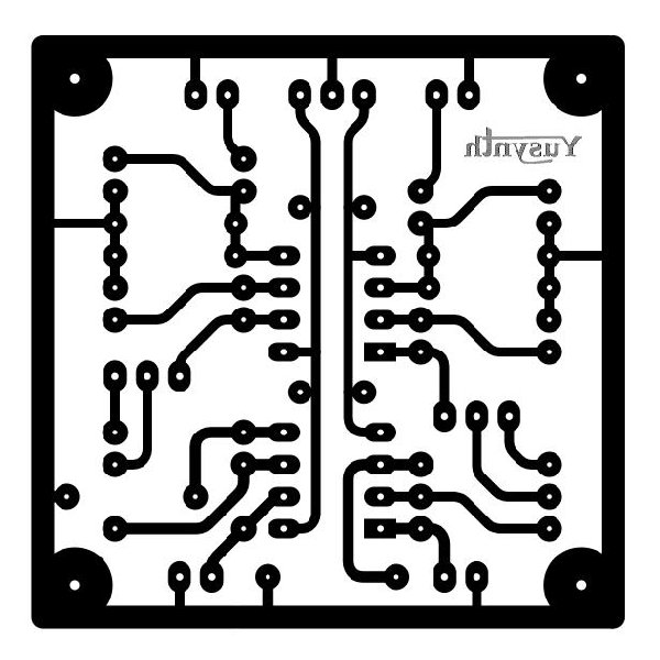
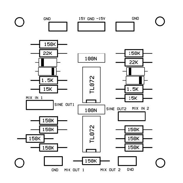
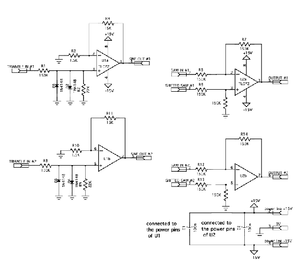
By the way, I found (and some other people did as well) that the internal modulation with a TRIANGLE shape was giving a result a bit too harsh, furthermore the fact of using an external mixer could be a poblem. Therefore I designed a small add-on board for this module that solves all these issues by providing two TRIANGLE to SINEWAVE converters and two MIXERs to improve the SAWANIMATOR.
It is not yet available on my site but here are the PCB layouts and schematic. The wiring diagram will come soon but it consists mainly in inserting the wave converter between the LFO out of the SAW-ANIMATOR and the MODULATION IN; and the MIXER is connected using the SAW IN and SAWANIM output to the mixer inputs and the mixer output to the output jack. A switch may be use to toggle from the unmixed to the mixed version.
| Description: |
| 300 dpi image, it should scale correctly when printed though it looks big on the screen |
|
| Filesize: |
53.64 KB |
| Viewed: |
608 Time(s) |
| This image has been reduced to fit the page. Click on it to enlarge. |
|
| Description: |
|
| Filesize: |
40.34 KB |
| Viewed: |
626 Time(s) |
| This image has been reduced to fit the page. Click on it to enlarge. |
|
| Description: |
|
| Filesize: |
34.88 KB |
| Viewed: |
766 Time(s) |
| This image has been reduced to fit the page. Click on it to enlarge. |
|
_________________
Yves
Last edited by yusynth on Tue Dec 08, 2009 12:02 pm; edited 4 times in total |
|
|
Back to top
|
|
|
Thalassa
Joined: Jan 27, 2006
Posts: 95
Location: Spain
Audio files: 5
|
| Posted: Tue Jun 02, 2009 12:35 am Post subject:
|
|
|
Hello Yves, thanks for the information I will make the saw animator with this add . Good to know this mod before to finish the module
_________________
http://www.corsynth.com |
|
|
Back to top
|
|
|
numbertalk
Joined: May 05, 2008
Posts: 992
Location: Austin, TX
Audio files: 5
|
| Posted: Thu Jun 04, 2009 5:54 am Post subject:
|
|
|
EDIT: Disregard - the image looked big but when I printed it it was scaled correctly already.
Thanks,
Paul |
|
|
Back to top
|
|
|
Thalassa
Joined: Jan 27, 2006
Posts: 95
Location: Spain
Audio files: 5
|
|
|
Back to top
|
|
|
yusynth
Joined: Nov 24, 2005
Posts: 1314
Location: France
|
| Posted: Fri Jun 12, 2009 12:51 am Post subject:
|
|
|
Nice demo 
_________________
Yves |
|
|
Back to top
|
|
|
Thalassa
Joined: Jan 27, 2006
Posts: 95
Location: Spain
Audio files: 5
|
| Posted: Thu Oct 08, 2009 11:02 am Post subject:
|
|
|
Hello Yves , playing with the saw animator I've realized that I've made a mistake and I didn't used switched jacks on the mod inputs and also on the saw2 input. So I was checking which one to buy but I'm not sure.
Can you tell me which model jacks are you using ( switched and not switched) ?
I always buy Neutrik conectors on mouser
Thanks :
Pablo
_________________
http://www.corsynth.com |
|
|
Back to top
|
|
|
yusynth
Joined: Nov 24, 2005
Posts: 1314
Location: France
|
| Posted: Thu Oct 08, 2009 11:39 am Post subject:
|
|
|
Hi Pablo
I am using these :
| Quote: | | http://www.musikding.de/product_info.php/info/p1140_6-3mm-Mono-jack-with-switch.html |
_________________
Yves |
|
|
Back to top
|
|
|
Thalassa
Joined: Jan 27, 2006
Posts: 95
Location: Spain
Audio files: 5
|
| Posted: Thu Oct 08, 2009 11:59 am Post subject:
|
|
|
Thanks for your reply and it's great because I was going to order few things from musikding.de
_________________
http://www.corsynth.com |
|
|
Back to top
|
|
|
kx
Joined: Dec 05, 2009
Posts: 17
Location: New Zealand
|
| Posted: Sat Dec 05, 2009 7:13 pm Post subject:
|
|
|
Hi everyone,
I've built a Yusynth Saw Animator and I'm just wondering if anyone might have any ideas about troubleshooting it...
I've made the original PCB with the addon on one board, and included switches to choose between sin or triangle modulation. The LFO circuit works great, the addon circuit all works great, but there's just a small strange thing with the wave 'shape' part of the circuit.
I'm feeding it not-quite-perfect sawtooth waves that are about +/- 4v as shown below :

and the best output waveform I can get with the 'shape' trimmer (200k) is this :

The balance trimmer works fine and all. The thing is, it is behaving exactly the same for both channels, so I don't really think it's an etching problem or soldering mistake..
Does anyone have any ideas of things to check that I could have missed? Or is it maybe just because I'm feeding it an imperfect waveform?
Thanks a lot in advance for any replies  [/img] [/img] |
|
|
Back to top
|
|
|
numbertalk
Joined: May 05, 2008
Posts: 992
Location: Austin, TX
Audio files: 5
|
| Posted: Sat Dec 05, 2009 8:10 pm Post subject:
|
|
|
| I know this circuit is very particular in regards to requiring a 10Vp-p signal that is centered around 0V. |
|
|
Back to top
|
|
|
kx
Joined: Dec 05, 2009
Posts: 17
Location: New Zealand
|
| Posted: Sat Dec 05, 2009 9:13 pm Post subject:
|
|
|
| hmm, maybe I should just wait till I make my TH-101 which can give me saw waves to the right specification |
|
|
Back to top
|
|
|
yusynth
Joined: Nov 24, 2005
Posts: 1314
Location: France
|
| Posted: Sun Dec 06, 2009 2:20 am Post subject:
|
|
|
Imperfect on input... imperfect on output...
Anyway you could expect a better output if your imperfect signal is perfectly balanced. Did you check for an offset in your imperfect sawtooth ? That is using your scope in DC mode and setting the 0V line at mid height of the scope screen, the signal is well balanced around the middle line ?
If not then you can't expect to obtain a good output signal.
_________________
Yves |
|
|
Back to top
|
|
|
|

 Forum index » DIY Hardware and Software » YuSynth


