| Author |
Message |
Scott Stites
Janitor


Joined: Dec 23, 2005
Posts: 4127
Location: Mount Hope, KS USA
Audio files: 96
|
 Posted: Sat Aug 09, 2008 5:07 pm Post subject: Posted: Sat Aug 09, 2008 5:07 pm Post subject:
|
  |
|
Chill away!
I have to go back through the breadboard and make sure I have everything recorded - some of it was done last night when I should have been (or actually may have been) sleeping. I'll also burn a sample of it in action.
I'll probably refine it, document it, then set it aside and try Ian's approach. TH emailed me the Electronotes reference to the single bus keyboard saying it should work, and could probably be around a three chip app with the parts available nowadays, which is much less than what's on my breadboard (though I don't think I'm using fifty percent of what's on the breadboard). I'm going to have to break down and buy some Electronotes, I guess. I plan on studying Ian's wind controller as well. Getting to know the technique I think will be very useful.
Cheerios,
Scott
_________________
My Site |
|
|
Back to top
|
|
 |
State Machine
Janitor

Joined: Apr 17, 2006
Posts: 2809
Location: New York
Audio files: 24
|
| Posted: Sat Aug 09, 2008 5:30 pm Post subject:
|
|
|
| Quote: | | I'm going to have to break down and buy some Electronotes, |
OK there Scott. I have been wrestling if I should break down and get some of the Electronotes myself. Probably save myself from re-inventing things. Sometimes though, the fun part is that you come up with your own original stuff then bang it up against what has been done. What your doing right now.
Me personally, I like to see whats out there and then see how I can cram it into a PLD or MCU application and perform the circuit functions algorithmically.
Anyhow, I sent you some information in your mail box you might like. 
Bill |
|
|
Back to top
|
|
|
State Machine
Janitor
Joined: Apr 17, 2006
Posts: 2809
Location: New York
Audio files: 24
|
| Posted: Sat Aug 09, 2008 8:11 pm Post subject:
|
|
|
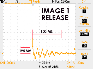
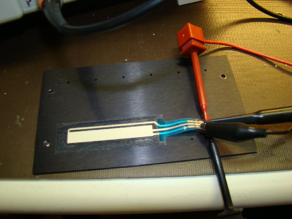
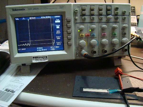
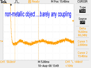
I tested a 50 mm softpot this evening just to see how it behaves. The fourth picture below shows how I mounted it. I think it's very important that these get mounted to a firm surface. These pots had an adhesive backing so you can stick them anywhere. I chose a blank metal plate. I biased the pot with a 10V power supply and attached the scope to the center wiper as shown in the last picture.
IMAGE 1 shows a typical release with a worse case bounce of about 100 milliseconds. The interesting thing here is that no bounce ever goes beyond about 200 millivolts so you can reference a comparator to 300 millivolts and get a clean pulse just about every time. A Shockley diode reference would work fine for this.
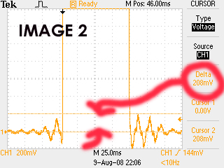
IMAGE 2 this image shows the lead edge bounce which is never as great as the trail edge bounce. Again, I had repeatedly pressed the softpot and never got anything higher than about 200 +/- 10 millivolts.
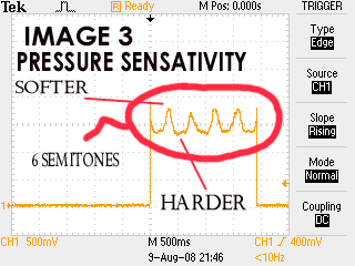
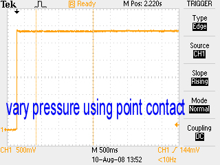
IMAGE 3 this image shows an interesting property of the softpot and that is, it's pressure sensitivity [spelling wrong in the image]. This oscillograph shows a press for about 2 seconds. During this time I press the pot surface, I vary the pressure with my appendage while the graph reveals about a 6 semitone span when driving a 1V/Octave VCO. Thus, the softpot is pressure sensitive. The one thing to watch is that the harder you press, the lower the voltage so an oscillator would lower in frequency. This could make for some nice vibrato effects though.
Hope some of this information helps others ........
Bill
| Description: |
|
| Filesize: |
101.69 KB |
| Viewed: |
31046 Time(s) |
|
| Description: |
|
| Filesize: |
105.13 KB |
| Viewed: |
31046 Time(s) |
|
| Description: |
|
| Filesize: |
108.23 KB |
| Viewed: |
31046 Time(s) |
|
| Description: |
|
| Filesize: |
1.08 MB |
| Viewed: |
411 Time(s) |
| This image has been reduced to fit the page. Click on it to enlarge. |
|
| Description: |
|
| Filesize: |
933.05 KB |
| Viewed: |
404 Time(s) |
| This image has been reduced to fit the page. Click on it to enlarge. |
|
|
|
|
Back to top
|
|
|
Scott Stites
Janitor
Joined: Dec 23, 2005
Posts: 4127
Location: Mount Hope, KS USA
Audio files: 96
|
| Posted: Sun Aug 10, 2008 1:07 am Post subject:
|
|
|
Thanks Bill! 200 ms of bounce was what the problem was getting a good voltage with my first go. Mine is not glued to anything, and I imagine a portion of the bounce I'm seeing is just that. I don't have a decent surface yet to put it on (my brother is preparing a nice chunk of walnut for me) and there's really no good way to tack the things down otherwise.
And pressure sensitivity - you're right again. Generally it gets more obvious towards the high end. It does make for a nice vibrato; so does rolling the finger on the Softpot. One has to take care with held notes with enough pressure to bend the note and suddenly releasing - it'll cause a bit of a shift. In fact, I thought "WTF? Why is that happening?" 'til I measured the voltage coming off the ribbon itself. It's a neat effect once one prepared for it though...kinda Asian music sounding if you do it right.
And, oh, my, my circuit is working just as I wanted it to - rock solid, responsive, and fun. I'm going to love this new addition to my synthy family. I think I'm going to put an extra voltage input to it as a substitute for the voltage at the top of the SoftPot - just insert an LFO and control the level with the Ribbon controller, for example.
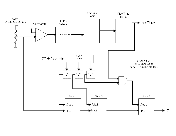
I've uploaded the block diagram of what my circuit currently is.
There is, of course, still the comparator. I convert the rising edge and falling edge of the comparator into high and low pulses (both are positive going, and coincident with the rising and falling edge of the raw comparator). These are fed into a D flip flop, which accepts only the first comparator pulse and ignores any other inadvertent comparator pulses over a given period of time. It generates a nice clean, debounced comparator signal.
I used a couple of CD40106 stages to delay the rising portion of that clean comparator wave, for reasons to be explained shortly.
The wiper voltage goes to a three stage analog shift register made up of three Sample and Hold blocks. The shift registers are clocked sequentially bya CD4017 that resets at stage four so that only the first three outputs repeat. The first two S&H's are clocked continuously, regardless of the state of the comparator. The third sample and hold, which is the output voltage, is only clocked when the comparator is high.
This arrangement guarantees that the voltage output is sampled before the wiper voltage ever makes that dive down into comparator land. It will always put out a voltage that occured two clock cycles previous, before the wiper was released and the wiper voltage fluctuated downwards.
The first two shift registers are always clocked, so they will always "know" what the current wiper voltage is. The comparator pulse rise time is offset long enough for a couple of clock cycles to occur before shift register 3 is allowed to sample again. This allows a smooth transition between voltages when the appendage is lifted from the ribbon controller then set back down. Without that, sometimes the new voltage cycling through would be some very low value and "thump" the CV output. With this arrangement, the first two sample and holds are at wiper voltage before the third S&H is allowed to take the voltage and output it as CV.
The fall time of this modified comparator signal is left unaltered - there is no delay, other than normal propagation, between when the actual comparator goes low and this modified signal goes low.
As weird as this arrangement may seem, it works like a bat out of hell, and I'm very, very pleased with it.
Ian - I used LF398s for the S&Hs. I generally just copy Rene Schmitz's YASH, because it's extremely easy and fast to do on the breadboard. Thing is, the YASH has a fair amount of droop. I multiplied the pulse width and S&H cap capacity by a factor of 10, and the performance is really nice, though I have yet to make a droop measurement. By ear, I'm very happy indeed and would have no reason to change it.
Cheerios,
Scott
| Description: |
|
| Filesize: |
11.64 KB |
| Viewed: |
615 Time(s) |
| This image has been reduced to fit the page. Click on it to enlarge. |
|
_________________
My Site |
|
|
Back to top
|
|
|
frijitz
Joined: May 04, 2007
Posts: 1734
Location: NM USA
Audio files: 54
|
| Posted: Sun Aug 10, 2008 8:44 am Post subject:
|
|
|
Bill/Scott --
Great work guys! This is getting really interesting. I used to play cello a bit and have always wanted to try some kind of monochord.
Interesting that the "bounce" actually looks more like a small ringing. In fact, unless my eyes are failing me again, it's at exactly 60 Hz! Maybe there could be an easier way to get rid of it. This makes more sense to me, because it is a bit difficult to see how a squishy polymer would bounce mechanically like a switch.
The pressure effect. You might want to check whether the pitch shift is merely due to a length change caused by your finger squishing out or an actual property of the polymer. Maybe push with a stick or something?
Keep it up!

Ian |
|
|
Back to top
|
|
|
Scott Stites
Janitor
Joined: Dec 23, 2005
Posts: 4127
Location: Mount Hope, KS USA
Audio files: 96
|
| Posted: Sun Aug 10, 2008 10:11 am Post subject:
|
|
|
| Quote: | | The pressure effect. You might want to check whether the pitch shift is merely due to a length change caused by your finger squishing out or an actual property of the polymer. Maybe push with a stick or something? |
I think that's certainly what I'm seeing. If I play it with the soft edge of my long nose pliers, the effect is not nearly so pronounced. The data sheets always mention a stylus of some sort, which at higher ranges (voltages) makes playing the thing more precise. One of those ball point styluses....styli?....would be handy to have around.
| Quote: | | Interesting that the "bounce" actually looks more like a small ringing. |
Yes, "ringing" would be a more accurate description of it. I'm wondering: this is a very long, very, very thin layered tape. A conductor on one terminal and a resistive strip on the other terminal, separated by a very thin dielectric. Doesn't that pretty much make the thing a giant capacitor? The strip I'm working with is 500 mm.
_________________
My Site |
|
|
Back to top
|
|
|
blue hell
Site Admin

Joined: Apr 03, 2004
Posts: 24083
Location: The Netherlands, Enschede
Audio files: 278
G2 patch files: 320
|
| Posted: Sun Aug 10, 2008 10:31 am Post subject:
|
|
|
| Scott Stites wrote: | | a giant capacitor? |
Depends on the spacing of the conductors, but for shielded cable something like 100 pF / meter is what I use as a rule of thumb - so it wouldn't be really giant for half a meter.
_________________
Jan
also .. could someone please turn down the thermostat a bit.
 |
|
|
Back to top
|
|
|
State Machine
Janitor
Joined: Apr 17, 2006
Posts: 2809
Location: New York
Audio files: 24
|
| Posted: Sun Aug 10, 2008 10:35 am Post subject:
|
|
|
SCOTT:
| Quote: | | The wiper voltage goes to a three stage analog shift register made up of three Sample and Hold blocks. The shift registers are clocked sequentially bya CD4017 that resets at stage four so that only the first three outputs repeat. The first two S&H's are clocked continuously, regardless of the state of the comparator. The third sample and hold, which is the output voltage, is only clocked when the comparator is high. |
A discrete analog delay line. That is very nice solution If I were to do this in firmware using a small MCU with a 10-bit A/D converter (the norm in most MCU's now), your delay you created would be the equivalent to a (N-2) delay where "N-2" represents an earlier sample. When the event of releasing the softpot is detected, an earlier (N-2) sample would be used that represented the state of the wiper just before release. A circular buffer of 2 to 4 samples could be created, kept going round and round until I needed an earlier sample to use. However, the sample that I use would write out to a DAC to get infinite hold time.
I do like this approach your using and is as valid as any other and one of those S/H's with very low droop rate would solve this problem if sustain is very important to you. Seems like it's working well and thats a good thing.
A thought does come to mind concerning analog delays. Would a analog BBD device like the BL3208 (8 Pin DIP, nice and small, DIY friendly) be good in this application? I wonder if it would be too "dirty" or inaccurate? I quite honestly have little experience with them. I know you would need a two phase clock to drive it right? Just some thoughts here. Small Bear Electronics has them for about 3 bucks and change. Your final stage would use a single LF398 but the front end would be the BBD chip.
http://www.smallbearelec.com/Detail.bok?no=253
IAN:
| Quote: | | Interesting that the "bounce" actually looks more like a small ringing. In fact, unless my eyes are failing me again, it's at exactly 60 Hz! Maybe there could be an easier way to get rid of it. This makes more sense to me, because it is a bit difficult to see how a squishy polymer would bounce mechanically like a switch. |
Yes, it's more like ringing than it is "bounce" I will go back and measure the frequency of this ringing effect. Very good observation Ian 
| Quote: |
The pressure effect. You might want to check whether the pitch shift is merely due to a length change caused by your finger squishing out or an actual property of the polymer. Maybe push with a stick or something?
|
Oh yes, right. Another very good observation I will press using both a blunt metallic object and a non-metallic object to make observations on the ringing and pressure sensitivity effects. This will further characterize the softpot behavior. My guess it's due to the finger "squishing out" effect that gives the appearance of being pressure sensitive. Either way, however it's derived, it is sensitive to pressure simply because your finger, or other appendage, deforms
I will report my results .........
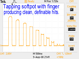
I do want to point out that these softpots would form the basis of a very nice analog trigger pad for electronic drums. The are not so sensitive that they false trigger all the time and they have just the right amount of sensitivity to even be great for "finger" drumming !!!! The oscillograph below shows the response of some finger tapping along the length ofhte softpot. I am impressed with the response and will inspire me to do more with these. This would make a great trigger pad for hte UD-1 or MPS drum voices !!!
Bill
| Description: |
|
| Filesize: |
115.72 KB |
| Viewed: |
30995 Time(s) |
|
|
|
|
Back to top
|
|
|
Scott Stites
Janitor
Joined: Dec 23, 2005
Posts: 4127
Location: Mount Hope, KS USA
Audio files: 96
|
| Posted: Sun Aug 10, 2008 11:00 am Post subject:
|
|
|
I'd think you'd need to clock the bejebus out of a 3207 to get a delay on the order of what's desirable here. Plus, 1024 caps stand more of a chance of introducing more error than 3. I'd think the cost and supporting circuitry of a BBD and two phase clock would amount to considerably more overhead than a couple of simple S&Hs, a cheapo CD4017 and a cheapo CD40106.
However - maybe we could go into business building discrete BBDs for physical modeling? That deal you pointed me to on EBAY would be a great start. 
_________________
My Site |
|
|
Back to top
|
|
|
State Machine
Janitor
Joined: Apr 17, 2006
Posts: 2809
Location: New York
Audio files: 24
|
| Posted: Sun Aug 10, 2008 11:06 am Post subject:
|
|
|
More observations ........
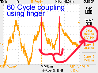
The pictures below prove that a) the material is not pressure sensitive. Something we all sort of concluded before I did this little experiment. A point contact with the pot using the blunt end of a dental tool, while applying varied pressure, does NOT change the output voltage.
b) the ringing is indeed 60 cycle, and would be most like 50 across the pond The ringing is due to most likely a capacitive coupling between the finger and potentiometer.
c) ringing is close to being eliminated when using a non-metallic stylus to put pressure on the softpot.
Bill
| Description: |
|
| Filesize: |
129.56 KB |
| Viewed: |
30986 Time(s) |
|
| Description: |
|
| Filesize: |
112.96 KB |
| Viewed: |
30986 Time(s) |
|
| Description: |
|
| Filesize: |
103.01 KB |
| Viewed: |
30986 Time(s) |
|
|
|
|
Back to top
|
|
|
State Machine
Janitor
Joined: Apr 17, 2006
Posts: 2809
Location: New York
Audio files: 24
|
| Posted: Sun Aug 10, 2008 11:11 am Post subject:
|
|
|
| Quote: | | I'd think you'd need to clock the bejebus out of a 3207 to get a delay on the order of what's desirable here. Plus, 1024 caps stand more of a chance of introducing more error than 3. I'd think the cost and supporting circuitry of a BBD and two phase clock would amount to considerably more overhead than a couple of simple S&Hs, a cheapo CD4017 and a cheapo CD40106. |
Thats what I might have expected. Once again, the cheapo chips rule !!
| Quote: | | However - maybe we could go into business building discrete BBDs for physical modeling? That deal you pointed me to on EBAY would be a great start. |
Hmmm, sounds luring but I think I will keep my day job ...
Bill |
|
|
Back to top
|
|
|
Scott Stites
Janitor
Joined: Dec 23, 2005
Posts: 4127
Location: Mount Hope, KS USA
Audio files: 96
|
| Posted: Sun Aug 10, 2008 11:13 am Post subject:
|
|
|
Well, actually 100 kHz clock wouldn't produce more than 5.12 ms latency. 200 kHz would render the same latency as the two sample and holds. However, the input/output to the BBD would need to be scaled considerably.
| Quote: | | Hmmm, sounds luring but I think I will keep my day job ... |
Are you sure? We could borrow my brother's flatbed for hauling around the PCBs
_________________
My Site |
|
|
Back to top
|
|
|
frijitz
Joined: May 04, 2007
Posts: 1734
Location: NM USA
Audio files: 54
|
| Posted: Sun Aug 10, 2008 11:35 am Post subject:
|
|
|
| Scott Stites wrote: | | However - maybe we could go into business building discrete BBDs for physical modeling? |
You mean like this?
http://home.comcast.net/~ijfritz/pm_cir3.htm
Ian |
|
|
Back to top
|
|
|
frijitz
Joined: May 04, 2007
Posts: 1734
Location: NM USA
Audio files: 54
|
| Posted: Sun Aug 10, 2008 11:47 am Post subject:
|
|
|
| State Machine wrote: | | More observations ........ |
Yep, you got it nailed now.
The ac pickup will depend a lot on your environment, whether you are grounded, how much your skin is conducting, etc. So maybe you need some careful filtering?
You might try rubbing some lotion into your skin and maybe hooking up a ground strap.
Ian |
|
|
Back to top
|
|
|
Scott Stites
Janitor
Joined: Dec 23, 2005
Posts: 4127
Location: Mount Hope, KS USA
Audio files: 96
|
| Posted: Sun Aug 10, 2008 9:55 pm Post subject:
|
|
|
I figure before the weekend was over, I should post a sample of this thing and hopefully y'all will understand why I get so excited about such things.
The ribbon controller is controlling a single Schmitz VCO3 through the 2040 Clone filter, then through a Wilson VCA. The gate output is gating one of my EGs, which is controlling the cutoff of the filter and the VCA. The ribbon controller is controlling both the VCO and the cutoff frequency of the 2040 filter.
It starts out with a lot of delay, with a soft attack, short release on the EG. I then switch to a sharper attack and release. After that I turn off the delay, after a while I set a longer release. Dang - should have put in a really long release to show how solid the S&H is.
Now, bear in mind this is a thin little ribbon laying on my bench surrounded by resistors and caps that were rejected from the project. The ribbon is very, very flexible and is plugged straight into the breadboard. I can't easily access the very lowest part of it, because it's in midair. Moreover, doing slides smoothly is hampered by the fact that it tends to "bunch up", so I have to kind of hold it down by the very edge when I'm sweeping my appendage over it. In a word, things will be much better when it's mounted to something solid and doesn't act like a Christmas bow.
Cheerios,
Scott
| Description: |
| First Sample of SoftPot Ribbon Controller |
|

Download |
| Filename: |
ribbon_control_first.mp3 |
| Filesize: |
4.24 MB |
| Downloaded: |
1266 Time(s) |
_________________
My Site |
|
|
Back to top
|
|
|
Coriolis

Joined: Apr 11, 2005
Posts: 616
Location: Stilling, Denmark
|
| Posted: Mon Aug 11, 2008 1:06 am Post subject:
|
|
|
Uh-ma-zing!
This has a lot of potential (can you hear the "I'm in for n pcb's" choir in the distance?).
For some reason I always assumed that a ribbon controller could basically make theremin-like legato-glissando sounds. But of course the ability to make it gate and trig things takes it way beyond that..
More! More!
C
_________________
Some Rubber Stamp Sound Effects - and other sound effects |
|
|
Back to top
|
|
|
Scott Stites
Janitor
Joined: Dec 23, 2005
Posts: 4127
Location: Mount Hope, KS USA
Audio files: 96
|
| Posted: Mon Aug 11, 2008 7:26 am Post subject:
|
|
|
Yep, having the gate and trigger outputs really expands the uses of it. It doesn't re-trigger (ie produce a new trigger when the note changes), but it does trigger/gate every time you apply the appendage.
In fact, this morning I was thinking it wouldn't be too far of a stretch to make the gate/trig/CV outputs alternate between a set of jacks, which would allow notes to overlap - it would be sort of a duophonic effect, or triphonic, etc., depending on how far you wanted to go with that.
Last night it also occured to me that the output could be quantized and bent/stretched around the quantized note, if my thinking is correct that is.
If you held the original voltage that is generated when you first apply the appendage through a sidechain, and quantized that voltage, then you could also subtract that voltage from the tracking sample and hold. Initially this voltage would be 0V. As you moved the appendage up and down the ribbon controller, the mixed voltage would begin to rise and fall around that 0V point. The quantized voltage would then be mixed with this voltage. This would slide the quantized voltage up and down, apply vibrato, etc., without stepping. When the appendage is lifted and reapplied, a new note is entered, and the process repeats.
Taking that concept a step further, one could conceivably use two sample and holds on the ribbon cable - one takes the initial appendage-on voltage, while the other continuously tracks the ribbon voltage. The initial-on voltage would be subtracted from the continuously variable voltage, providing a +/- control output which could be mixed with, say, a keyboard voltage. The effect would be that (using the keyboard as an example) - one could play the keyboard and press the ribbon controller at any point, then mix it with and bend the keyboard voltage up and down - the pressed position on the controller wouldn't matter. I suppose one would want either the gate or trigger output of the keyboard to reset the ribbon controller back to 0V, so the next note played wouldn't be bent to some unknown value. Or, just removing the appendage would put the voltage back to 0. This could be provided as an extra +/-V around center point voltage.
And, of course, there's nothing stopping one from applying a signal to the top or bottom (or two signals to both) of the ribbon controller and having a raw output that would directly variable attenuate a single input, or, perhaps, cross-mix two signals. The raw output would bypass the sample and hold so that high modulation frequencies could be on the applied signals, if desired.
Cheerios,
Scott
_________________
My Site |
|
|
Back to top
|
|
|
numbernone
Joined: Aug 16, 2006
Posts: 477
Location: new york city
|
| Posted: Mon Aug 11, 2008 7:30 am Post subject:
|
|
|
Man am I glad I asked what your new project was on the stribe thread... This sounds truly fantastic.
Comparing my own naive attempts at ribbon control with yours and reading the tech talk between you and Bill, reminds me very much of a favorite Simpsons episode... The family goes to Itchy and Scratchy land, during the big parade, an automaton Scratchy leans over and lifts the top of his head off showing off lots of circuits and lights and such. Marge says to Homer, " See all that stuff inside? Thats why your robot never worked." |
|
|
Back to top
|
|
|
frijitz
Joined: May 04, 2007
Posts: 1734
Location: NM USA
Audio files: 54
|
| Posted: Mon Aug 11, 2008 8:45 am Post subject:
|
|
|
Sounds great , Scott. No extra or missed triggers -- very robust.
| Scott Stites wrote: | | Yep, having the gate and trigger outputs really expands the uses of it. It doesn't re-trigger (ie produce a new trigger when the note changes), but it does trigger/gate every time you apply the appendage. |
So if you hold one appendage down and trill with another you don't get triggers? Or if you put down four appendages sequentially only the first generates the trigger?
On my wind controller I have two kinds of triggers -- one when you start a note by tonguing and another when you change fingerings (slurred notes). You could do something similar. The triggering you have would be like tonguing and you could add a differentiator (there he goes again) which fires a trigger when the voltage changes faster than a certain rate. So it wouldn't trigger while gliding, just when you slap down a new appendage.
Another idea would be to add a force sensor (maybe under the strip), to give you a touch sensitivity.
Just some thoughts based on things I've done, and of course you have your own requirements. But I think this little strip could be very expressive.
Ian |
|
|
Back to top
|
|
|
Scott Stites
Janitor
Joined: Dec 23, 2005
Posts: 4127
Location: Mount Hope, KS USA
Audio files: 96
|
| Posted: Mon Aug 11, 2008 8:55 am Post subject:
|
|
|
| Quote: | | So if you hold one appendage down and trill with another you don't get triggers? Or if you put down four appendages sequentially only the first generates the trigger? |
Right - just one trigger until all appendages are removed than applied again. This was how I originally envisioned a ribbon controller to work.
After playing with it a while, I can see where one would want to re-trigger with trills. Maybe not all the time (and re-triggering could be defeated under those circumstances), but re-triggering would certainly expand the expressiveness greatly when one wanted that sort of action.
| Quote: | | Just some thoughts based on things I've done, and of course you have your own requirements. |
Absolutely quite welcome - I just wasn't sure how one would do re-triggering, but your suggestions show how it could be done.
| Quote: | | Marge says to Homer, " See all that stuff inside? Thats why your robot never worked." |
I remember that one!
_________________
My Site |
|
|
Back to top
|
|
|
Scott Stites
Janitor
Joined: Dec 23, 2005
Posts: 4127
Location: Mount Hope, KS USA
Audio files: 96
|
| Posted: Mon Aug 11, 2008 8:58 am Post subject:
|
|
|
| Quote: | | I just wasn't sure how one would do re-triggering |
"Wasn't sure" = "Had no clue"
_________________
My Site |
|
|
Back to top
|
|
|
bugfight

Joined: Aug 02, 2007
Posts: 188
Location: Arlington, TX USA
|
| Posted: Mon Aug 11, 2008 2:36 pm Post subject:
|
|
|
this is very exciting. i especially like the relative output idea.
i've been meaning to make a ribbon controller since i first saw these softpots.
just goes to show if i procrastinate long enough someone will do it for me...
you guys are talking about your nose, right?
ok, so i think you better just start calling this device "the appendage" |
|
|
Back to top
|
|
|
Scott Stites
Janitor
Joined: Dec 23, 2005
Posts: 4127
Location: Mount Hope, KS USA
Audio files: 96
|
| Posted: Mon Aug 11, 2008 6:19 pm Post subject:
|
|
|
| Quote: | | i especially like the relative output idea. |
I think it's certainly doable. Use a S&H for note on reference and run that and the tracking S&H into a differential amplifier. I worked it out briefly over lunch, with several options of when and how to return to zero volts.
For example, if you're using a keyboard and you're actually bending notes rather than applying vibrato, you might want to bend up to a played note. The return to zero (no offset) of the relative output could reset to zero from the trigger signal of the keyboard.
You may want to return to zero when the keyboard gates.
You may want to return to zero just when you lift the...appendage. This would be sort of like a spring-centered control wheel.
I had fun working through the logic for any/all of these settings.
"Zero" itself wouldn't be all that difficult, even if there is S&H droop - zero would simply be setting up the reference S&H to track the tracking S&H. Since they're moving together, they should cancel each other out in times of zero.
| Quote: | | you guys are talking about your nose, right? |
But, of course!
| Quote: | | ok, so i think you better just start calling this device "the appendage" |
Good idea. It sure beats the hell out of "The Finger".
Cheerios,
Scott
_________________
My Site |
|
|
Back to top
|
|
|
State Machine
Janitor
Joined: Apr 17, 2006
Posts: 2809
Location: New York
Audio files: 24
|
| Posted: Tue Aug 12, 2008 9:32 am Post subject:
|
|
|
Scott, the sample certainly exemplifies the expressiveness attainable with this controller. The gate/trigger seem to work in flawless fashion
I really like this idea quoted below for the "duophonic" effect. This can turn out to be a very feature rich module if you wish to continue adding these sorts of features. Problem is, there are so many great ideas floating around, deciding which to pick may be the hardest part of the project. I do think that adding the BAR/DOT driver will add some nice "flash" to the project. I wonder if the softpots can be backlit?
| Quote: | | In fact, this morning I was thinking it wouldn't be too far of a stretch to make the gate/trig/CV outputs alternate between a set of jacks, which would allow notes to overlap - it would be sort of a duophonic effect, or triphonic, etc., depending on how far you wanted to go with that. |
Bill |
|
|
Back to top
|
|
|
Scott Stites
Janitor
Joined: Dec 23, 2005
Posts: 4127
Location: Mount Hope, KS USA
Audio files: 96
|
| Posted: Tue Aug 12, 2008 10:52 am Post subject:
|
|
|
I imagine if you laid the softpot on Plexiglass with LEDs underneath, it would show through. It'd probably look pretty cool, I imagine.
For me the bare minimum features would be a range control (to set the range of the ribbon) and perhaps an octave select, much like on keyboard. I've got a simple range control right now, but no octave select (yet).
The differential output is high on my list - seems I saw someone using a ribbon controller on a synth (maybe it was a CS80, dunno) that seemed to bend the notes the same, regardless of where the ribbon was touched. I'd find that immensely useful, myself, when using it as a modulation controller.
Ian's re-trigger idea has me by the short hairs, too. It's something I definitely want to try out and see if I can make it work, though I'll have to futz with it a bit, not having really worked a lot with differentiators (at least for figuring out how fast a signal moves). That will be educational for me, as well as fun.
I need to reduce the block diagram and complexity of the circuit, too. Right now it's overly complex, because the ideas sort of overlapped, and there are a few stages I think are unnecessary. Mainly the debouncing/edge detector. I think the comparator is solid enough to do its thing without that. I'll have to work with it a good while to make sure it actually doesn't make any difference when I take those sections out. I did pull the timing element out of the debouncer last night, and it didn't seem to make a bit of difference, which is a big clue that it's not necessary.
I've got a feeling I'll be off to Malaysia again, soon, so I'd like to get as much done before that as I can.
Cheerios,
Scott
_________________
My Site |
|
|
Back to top
|
|
|
|

 Forum index » DIY Hardware and Software
