| Author |
Message |
synthmonger
Joined: Nov 16, 2006
Posts: 578
Location: flada
Audio files: 3
|
 Posted: Thu Mar 26, 2009 12:58 pm Post subject:
Single transistor VCA circuit Posted: Thu Mar 26, 2009 12:58 pm Post subject:
Single transistor VCA circuit
Subject description: Korg used one right? |
  |
|
| Having trouble finding a schematic for it. I can't remember exactly what Korg circuit used it. Any help would be greatly appreciated! ;D |
|
|
Back to top
|
|
 |
Rykhaard
Joined: Sep 02, 2007
Posts: 1290
Location: Canada
|
| Posted: Thu Mar 26, 2009 1:28 pm Post subject:
|
|
|
| Rough memory but weren't it the MS-20? |
|
|
Back to top
|
|
|
slacker
Joined: Nov 18, 2007
Posts: 301
Location: England
Audio files: 11
G2 patch files: 1
|
|
|
Back to top
|
|
|
ChrisR

Joined: Feb 22, 2009
Posts: 24
Location: Dark side of the room
|
| Posted: Thu Mar 26, 2009 2:20 pm Post subject:
|
|
|
I was going to post the same reply as slacker 
I also looked at the schematics of the MS-10, and there seems to be a similar circuit in there. Would be nice if i could isolate it since i have a use for a simple vca.
Chris |
|
|
Back to top
|
|
|
slacker
Joined: Nov 18, 2007
Posts: 301
Location: England
Audio files: 11
G2 patch files: 1
|
| Posted: Thu Mar 26, 2009 2:33 pm Post subject:
|
|
|
| The WP20 from Music From Outer Space has basically the same thing as its VCA if that's any help. I think you can sub virtually any opamp for the LM3900. |
|
|
Back to top
|
|
|
synthmonger
Joined: Nov 16, 2006
Posts: 578
Location: flada
Audio files: 3
|
| Posted: Thu Mar 26, 2009 2:44 pm Post subject:
|
|
|
| Ah! Neat that looks like it'll work. I'll BB it and see how it operates. |
|
|
Back to top
|
|
|
richardc64

Joined: Jun 01, 2006
Posts: 679
Location: NYC
Audio files: 26
|
|
|
Back to top
|
|
|
Rykhaard
Joined: Sep 02, 2007
Posts: 1290
Location: Canada
|
| Posted: Thu Mar 26, 2009 3:21 pm Post subject:
|
|
|
Excellent! Thankee for posting that Richard! I'll be testing it out in my Lunetta machine!!  If it works well, I'll be building a bunch of them. (Not that I'm THAT concerned with audio quality in that machine, mind you. If it works well, I'll be building a bunch of them. (Not that I'm THAT concerned with audio quality in that machine, mind you.  ) ) |
|
|
Back to top
|
|
|
andrewF

Joined: Dec 29, 2006
Posts: 1176
Location: australia
Audio files: 4
|
| Posted: Sun Mar 29, 2009 6:32 am Post subject:
|
|
|
| slacker wrote: | | The WP20 from Music From Outer Space has basically the same thing as its VCA if that's any help. I think you can sub virtually any opamp for the LM3900. |
The 3900 is a Norton op-amp - current differencing rather than voltage.
A very special chip, Serge Tcherepnin probably exploited it more than anybody when it came to synth circuits.
can be sub'd with the LM2900 or MC3401 but not regular opamps |
|
|
Back to top
|
|
|
richardc64
Joined: Jun 01, 2006
Posts: 679
Location: NYC
Audio files: 26
|
|
|
Back to top
|
|
|
v-un-v
Janitor


Joined: May 16, 2005
Posts: 8932
Location: Birmingham, England, UK
Audio files: 11
G2 patch files: 1
|
| Posted: Sun Mar 29, 2009 12:07 pm Post subject:
|
|
|
Richard, can you provide a link to the circuit that uses the LM324? Thanks.
Tom
_________________
ACHTUNG!
ALLES TURISTEN UND NONTEKNISCHEN LOOKENPEEPERS!
DAS KOMPUTERMASCHINE IST NICHT FÜR DER GEFINGERPOKEN UND MITTENGRABEN! ODERWISE IST EASY TO SCHNAPPEN DER SPRINGENWERK, BLOWENFUSEN UND POPPENCORKEN MIT SPITZENSPARKSEN.
IST NICHT FÜR GEWERKEN BEI DUMMKOPFEN. DER RUBBERNECKEN SIGHTSEEREN KEEPEN DAS COTTONPICKEN HÄNDER IN DAS POCKETS MUSS.
ZO RELAXEN UND WATSCHEN DER BLINKENLICHTEN. |
|
|
Back to top
|
|
|
richardc64
Joined: Jun 01, 2006
Posts: 679
Location: NYC
Audio files: 26
|
|
|
Back to top
|
|
|
Clack

Joined: Aug 08, 2005
Posts: 438
Location: Walthamstow - london
Audio files: 5
G2 patch files: 1
|
| Posted: Fri Jul 31, 2009 4:41 am Post subject:
|
|
|
hey gonna just bring this thread back up, because I want to discuss reasons for vca designs.
im trying to build a stackable (CV can control more that one channel) vc-mixer with the most minimal but most readily low cost available parts (ssm parts would be amazing if they weren't so rare)
I want to know what are the reasons for using a transconductance op-amp or other desgin over just a simple transistor/op-amp vca design?
im guessing its because of
lower input impedance?
is there less of a linear response or the response is less manipulative?
lower dynamic range?
more susceptible to offset and therefore distortion?
are these assumption correct or relevant?
_________________
Clacktronics.co.uk
Last edited by Clack on Fri Jul 31, 2009 6:01 am; edited 1 time in total |
|
|
Back to top
|
|
|
richardc64
Joined: Jun 01, 2006
Posts: 679
Location: NYC
Audio files: 26
|
| Posted: Fri Jul 31, 2009 5:44 am Post subject:
|
|
|
I don't know about your assumptions, but my assumption is that one advantage of using an OTA is that it can be D.C. coupled. With no capacitor in the signal path it can operate with lower losses at low frequencies, down to slow-moving envelopes and LFO ranges. At higher audio frequencies there would be none of the phasing effects of capacitor coupling -- unless that would be what you wanted.
All the simpler designs discussed above generally need a capacitor somewhere in the signal path, at input, output or both, like the MS-20 or the WP-20.
I'm sure someone here can correct my simplistic reasoning.
_________________
Revenge is a dish best served with a fork... to the eye |
|
|
Back to top
|
|
|
JovianPyx

Joined: Nov 20, 2007
Posts: 1988
Location: West Red Spot, Jupiter
Audio files: 224
|
| Posted: Fri Jul 31, 2009 7:49 am Post subject:
|
|
|
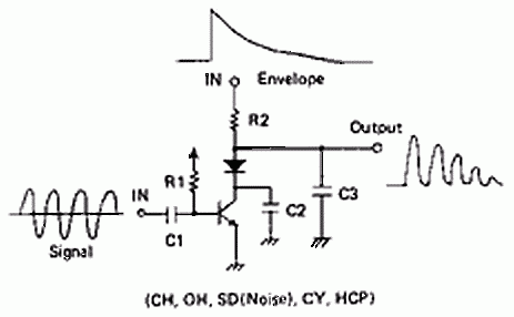
One reason for using an OTA type VCA over a single transistor is that with the single transistor VCA, the output's voltage will always be on one side of zero volts, either above or below depending on the circuit. You can see this with the drawing above that shows input and output waveforms.
An OTA will give an output that looks like the envelope is copied on both sides of zero volts.
The main effect of this is that the control voltage will feed through to the output with the single transistor VCA and will not feed through to the output with the OTA VCA.
The feed through is usually something undesired. Your milage may vary.
_________________
FPGA, dsPIC and Fatman Synth Stuff
Time flies like a banana.
Fruit flies when you're having fun.
BTW, Do these genes make my ass look fat?
corruptio optimi pessima
|
|
|
Back to top
|
|
|
richardc64
Joined: Jun 01, 2006
Posts: 679
Location: NYC
Audio files: 26
|
| Posted: Fri Jul 31, 2009 8:38 am Post subject:
|
|
|
| ScottG wrote: | | ...with the single transistor VCA, the output's voltage will always be on one side of zero volts, either above or below depending on the circuit. You can see this with the drawing above that shows input and output waveforms. |
Capacitor coupling at the output doesn't correct that? The output remains "flatline" at the top or bottom, depending?
_________________
Revenge is a dish best served with a fork... to the eye |
|
|
Back to top
|
|
|
Clack
Joined: Aug 08, 2005
Posts: 438
Location: Walthamstow - london
Audio files: 5
G2 patch files: 1
|
| Posted: Fri Jul 31, 2009 10:28 am Post subject:
|
|
|
Is it because BJT's only work in one direction?
getting to basic electronics here then
_________________
Clacktronics.co.uk |
|
|
Back to top
|
|
|
JovianPyx
Joined: Nov 20, 2007
Posts: 1988
Location: West Red Spot, Jupiter
Audio files: 224
|
| Posted: Fri Jul 31, 2009 12:10 pm Post subject:
|
|
|
| richardc64 wrote: | | ScottG wrote: | | ...with the single transistor VCA, the output's voltage will always be on one side of zero volts, either above or below depending on the circuit. You can see this with the drawing above that shows input and output waveforms. |
Capacitor coupling at the output doesn't correct that? The output remains "flatline" at the top or bottom, depending? |
Yes, capacitor coupling will result in the energy distribution being the same above and below zero, but there will still be a remnant of the straight line at the bottom of the envelope. That won't happen with the OTA VCA because the same envelope shape is copied to both the positive and negative halves of the signal. Also, the size of the capacitor will affect exactly what happens.
IMO, unless you have a good technical or application-based reason to use this type of VCA, I would avoid it. I realize that it's simplicity and low cost makes it attractive, but if it sacrifices what you want to hear, or adds an objectionable quality then it's value is quite a bit less. There are many reasons why you don't find this in high end gear.
_________________
FPGA, dsPIC and Fatman Synth Stuff
Time flies like a banana.
Fruit flies when you're having fun.
BTW, Do these genes make my ass look fat?
corruptio optimi pessima
|
|
|
Back to top
|
|
|
JovianPyx
Joined: Nov 20, 2007
Posts: 1988
Location: West Red Spot, Jupiter
Audio files: 224
|
| Posted: Fri Jul 31, 2009 12:12 pm Post subject:
|
|
|
| Mr Clack wrote: | Is it because BJT's only work in one direction?
getting to basic electronics here then |
More because it's a single ended circuit, which is easy to do with a single BJT (or FET for that matter) and a single supply.
_________________
FPGA, dsPIC and Fatman Synth Stuff
Time flies like a banana.
Fruit flies when you're having fun.
BTW, Do these genes make my ass look fat?
corruptio optimi pessima
|
|
|
Back to top
|
|
|
Clack
Joined: Aug 08, 2005
Posts: 438
Location: Walthamstow - london
Audio files: 5
G2 patch files: 1
|
| Posted: Fri Jul 31, 2009 12:20 pm Post subject:
|
|
|
yes, it was just for the sake of discussion, I was just trying to make it clear to myself why a OTA is used ... how the transistor falls flat in comparason with an op-amp
besides lm13700's (£0.90) arn't that pricey for what they give
thanks for the info both of you, it made things more understandable
I also found this using CMOS MOSFETs by Osamu Hoshuyama
http://www5b.biglobe.ne.jp/~houshu/synth/VcaMos0210.GIF
of course though 'output has much distortion'
_________________
Clacktronics.co.uk |
|
|
Back to top
|
|
|
JovianPyx
Joined: Nov 20, 2007
Posts: 1988
Location: West Red Spot, Jupiter
Audio files: 224
|
| Posted: Fri Jul 31, 2009 12:50 pm Post subject:
|
|
|
Yes, I've seen that too, he's quite a clever guy.
A word about distortion - it's not always bad. In fact, as you know, the most common "effect pedal" for electric guitar players is a distortion box. Some distortion is good, others is bad. The ear will always tell you the difference. With synths, there are many kinds of distortion, again, some sounds good, some is horrible. For example, any waveshaper is really a distortion circuit because it's output is a distorted version of it's input. That said, I wouldn't necessarily dismiss his circuit until it's breadboarded for a listen.
_________________
FPGA, dsPIC and Fatman Synth Stuff
Time flies like a banana.
Fruit flies when you're having fun.
BTW, Do these genes make my ass look fat?
corruptio optimi pessima
|
|
|
Back to top
|
|
|
Tim Servo

Joined: Jul 16, 2006
Posts: 924
Location: Silicon Valley
Audio files: 11
|
| Posted: Sat Aug 01, 2009 5:45 pm Post subject:
|
|
|
[quote="Clack"]hey gonna just bring this thread back up, because I want to discuss reasons for vca designs.
im trying to build a stackable (CV can control more that one channel) vc-mixer with the most minimal but most readily low cost available parts (ssm parts would be amazing if they weren't so rare)
quote]
Hey Clack,
If you're trying to build a VC mixer, you should check out the SSM2164 Quad VCA chip. Four expo response VCAs on a single chip, and available fairly cheap. The VCAs have VERY wide dynamic range and are very quiet. This is a currently available chip, made by Analog Devices and CoolAudio, and available from several sources. The CV inputs have low impedance (<5k) so you'll want to drive them with an op-amp buffer, but you can use one inverting buffer to drive all four sections on the chip if you want. Use a linear pot to provide the CV and you're jamming (that's why they made the VCAs on the chip expo - so you get a correct sounding response when driving them from a linear source). The CV range is roughly +3.3V (100dB attenuation) to 0V (no attenuation). You can even go slightly negative on the CV (about -0.6V) and get a bit of gain, giving you a dynamic range of 120dB!
Tim (Mr. Chips) Servo |
|
|
Back to top
|
|
|
CJ Miller

Joined: Jan 07, 2007
Posts: 368
Location: 127.0.0.1
|
| Posted: Sun Aug 02, 2009 2:23 pm Post subject:
|
|
|
Simple VCAs are very cool, and definately have their uses. These single-transistor types were used in Korg MS synths, and also in most drum machines. If you want ideas on how to make a complete synth with a handful of transistors, check out drum machine schematics. We're talking linear VCOs, single-supply everything. Lots of fun noises to be had.
But I need to agree with Tim. If you want simple VCAs for a mixer, you are better off with something more robust. Something with a small footprint and doesn't require much trimming. $5 for a VCA chip might not sound cheap, but you get ultra low noise and lose the CV rejection and offset problems. |
|
|
Back to top
|
|
|
jean-louise

Joined: Apr 27, 2009
Posts: 73
Location: berlin
Audio files: 2
|
| Posted: Tue Aug 25, 2009 3:29 am Post subject:
|
|
|

is that a NPN transistor?
thanx!
jan |
|
|
Back to top
|
|
|
jean-louise
Joined: Apr 27, 2009
Posts: 73
Location: berlin
Audio files: 2
|
| Posted: Tue Aug 25, 2009 4:29 pm Post subject:
|
|
|
ok, i found it out thanks to breadboard, it works with NPN. also an input attenuator is good to avoid/provide some dirtiness.
anybody has a suggestion as what to use for a coupling capacitor?
the 100nF one i had at hand seems far too small - when i turn down the filter cutoff there's nothing instead of the bass frequencies.. 
and does it matter wether i put it at the input or the output of the vca?
jan |
|
|
Back to top
|
|
|
|

 Forum index » DIY Hardware and Software