| Front Page | Radio | Media | Forum | Wiki | Links |

and electronic music
|
|
Dedicated to
experimental electro-acoustic and electronic music |
|
|
|
 Forum index » DIY Hardware and Software » Lunettas - circuits inspired by Stanley Lunetta Forum index » DIY Hardware and Software » Lunettas - circuits inspired by Stanley Lunetta |
|
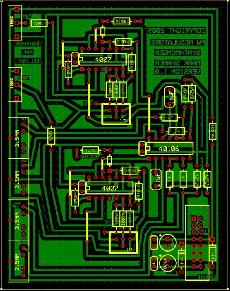
CMOS Pulsewidth Modulators
|
 
|
Moderators: mosc
Page 1 of 1 [9 Posts] |
View unread posts View new posts in the last week Mark the topic unread :: View previous topic :: View next topic |
| Author | Message | |||||||||||||||||||
|---|---|---|---|---|---|---|---|---|---|---|---|---|---|---|---|---|---|---|---|---|
|
synthmonger
Joined: Nov 16, 2006 Posts: 578 Location: flada Audio files: 3 |
|
|||||||||||||||||||
|
|
||||||||||||||||||||
DGTom
 Joined: Dec 08, 2008 Posts: 211 Location: Adelaide Audio files: 3 G2 patch files: 1 |
|
|||||||||||||||||||
|
|
||||||||||||||||||||
|
synthmonger
Joined: Nov 16, 2006 Posts: 578 Location: flada Audio files: 3 |
|
|||||||||||||||||||
|
|
||||||||||||||||||||
|
synthmonger
Joined: Nov 16, 2006 Posts: 578 Location: flada Audio files: 3 |
|
|||||||||||||||||||
|
|
||||||||||||||||||||
|
synthmonger
Joined: Nov 16, 2006 Posts: 578 Location: flada Audio files: 3 |
|
|||||||||||||||||||
|
|
||||||||||||||||||||
|
DGTom
Joined: Dec 08, 2008 Posts: 211 Location: Adelaide Audio files: 3 G2 patch files: 1 |
|
|||||||||||||||||||
|
|
||||||||||||||||||||
|
monokinetic
Joined: Aug 01, 2006 Posts: 100 Location: prague |
|
|||||||||||||||||||
|
|
||||||||||||||||||||
|
synthmonger
Joined: Nov 16, 2006 Posts: 578 Location: flada Audio files: 3 |
|
|||||||||||||||||||
|
|
||||||||||||||||||||
|
synthmonger
Joined: Nov 16, 2006 Posts: 578 Location: flada Audio files: 3 |
|
|||||||||||||||||||
|
|
||||||||||||||||||||
|
|
Moderators: mosc
Page 1 of 1 [9 Posts] |
View unread posts View new posts in the last week Mark the topic unread :: View previous topic :: View next topic |
|
Forum index » DIY Hardware and Software » Lunettas - circuits inspired by Stanley Lunetta |
|
You cannot post new topics in this forum You cannot reply to topics in this forum You cannot edit your posts in this forum You cannot delete your posts in this forum You cannot vote in polls in this forum You cannot attach files in this forum You can download files in this forum |