| Author |
Message |
j.dilisio

Joined: May 19, 2009
Posts: 200
Location: baltimore
|
 Posted: Tue Jun 30, 2009 3:28 pm Post subject: Posted: Tue Jun 30, 2009 3:28 pm Post subject:
 Simple Glide/Slew/Lag/Portamento.. Simple Glide/Slew/Lag/Portamento..
Subject description: Should this work? |
  |
|
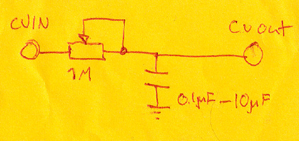
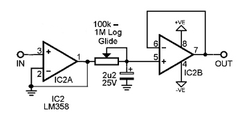
Here's a beginner question...
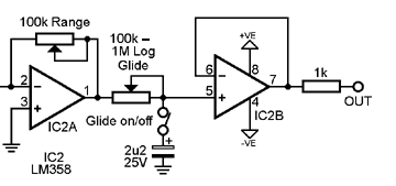
Someone gave me the following schematic for a simple glide circuit.
Should this work?
I tried it and found that while it does add some Lag to a CV signal, it also attenuates it.
I'm using a 100k pot and a 1uF cap just because that's what I had lying around so there's not much lag effect.
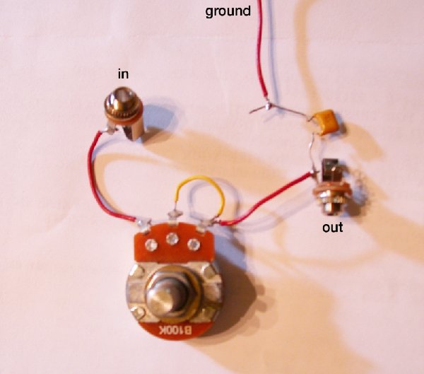
I've also attached an image of my attempt to test it.
Any ideas?
| Description: |
|
| Filesize: |
424.11 KB |
| Viewed: |
694 Time(s) |
| This image has been reduced to fit the page. Click on it to enlarge. |
|
| Description: |
|
| Filesize: |
300.2 KB |
| Viewed: |
605 Time(s) |
| This image has been reduced to fit the page. Click on it to enlarge. |
|
|
|
|
Back to top
|
|
 |
Tim Servo

Joined: Jul 16, 2006
Posts: 924
Location: Silicon Valley
Audio files: 11
|
| Posted: Tue Jun 30, 2009 4:03 pm Post subject:
Simple Glide/Slew/Lag/Portamento... |
|
|
Hey JD,
Well, that circuit is really close. What you need to do is add an op-amp buffer to the input, and another one to the output. The idea behind the buffers is that they isolate the circuit. Otherwise, the load that the glide circuit places on your CV source changes a lot depending on what the glide setting is.
What you're looking for is a "voltage follower" or "unity gain buffer." The circuits are REALLY simple, and you can get a single 8-pin IC that contains the two op-amps you'll need. Of course, you're going to need a power supply, but that's something you'll need for almost any synth circuit. Do a Google search for those buffers and I bet you'll find a ton of useful info.
Tim (sometimes useful) Servo |
|
|
Back to top
|
|
|
synthmonger
Joined: Nov 16, 2006
Posts: 578
Location: flada
Audio files: 3
|
| Posted: Tue Jun 30, 2009 6:39 pm Post subject:
|
|
|
I'm not sure how you have your jacks grounded but they don't look like they have wires tied to ground. Don't forget those!
_________________
Youtube!
modular demos!
Whacky tunes! |
|
|
Back to top
|
|
|
j.dilisio
Joined: May 19, 2009
Posts: 200
Location: baltimore
|
| Posted: Tue Jun 30, 2009 6:47 pm Post subject:
|
|
|
well heres another question..
If this works I'm planning on ultimately using Banana jacks hense the lack of ground to the jacks.
I've never tried Bananifying anything before, but thats how it works right?
You just don't ground the jacks? |
|
|
Back to top
|
|
|
synthmonger
Joined: Nov 16, 2006
Posts: 578
Location: flada
Audio files: 3
|
| Posted: Tue Jun 30, 2009 6:50 pm Post subject:
|
|
|
Right. Though it never hurts to have a banana to 1/4" 1/8" inch jack module. ;D If you do plan on running the banana output to a computer/amp or whatever then you must have a common ground obviously.
_________________
Youtube!
modular demos!
Whacky tunes! |
|
|
Back to top
|
|
|
j.dilisio
Joined: May 19, 2009
Posts: 200
Location: baltimore
|
|
|
Back to top
|
|
|
widdly
Joined: Jun 25, 2007
Posts: 268
Location: singapore
G2 patch files: 2
|
| Posted: Wed Jul 01, 2009 7:50 am Post subject:
|
|
|
| not quite. The first opamp is non-inverting, and the second opamp is inverting. So you end up with an upside down cv. If you ditch the 100k pot and wire the first opamp like the second you will be in business. |
|
|
Back to top
|
|
|
fonik

Joined: Jun 07, 2006
Posts: 3950
Location: Germany
Audio files: 23
|
| Posted: Wed Jul 01, 2009 8:50 am Post subject:
|
|
|
| widdly wrote: | | The first opamp is non-inverting, and the second opamp is inverting. |
just the other way around 
the 1st OpAmp is set as inverting amplifier to enable multiple inputs.
the 2nd OpAmp is set as non-inverting voltage follower.
if you set the 1st like the 2nd, you cannot use multiple inputs (mix). however, i think you are not after mixing multiple inputs anyways.
_________________

cheers,
matthias
____________
Big Boss at fonitronik
Tech Buddy at Random*Source |
|
|
Back to top
|
|
|
j.dilisio
Joined: May 19, 2009
Posts: 200
Location: baltimore
|
|
|
Back to top
|
|
|
synthmonger
Joined: Nov 16, 2006
Posts: 578
Location: flada
Audio files: 3
|
| Posted: Wed Jul 01, 2009 9:12 am Post subject:
|
|
|
The cap size controls how long the sampled voltage or 'glide' will last while the potentiometer just fine tunes it. With a 1M pot and that cap size you'll have a nice range.
_________________
Youtube!
modular demos!
Whacky tunes! |
|
|
Back to top
|
|
|
fonik
Joined: Jun 07, 2006
Posts: 3950
Location: Germany
Audio files: 23
|
| Posted: Wed Jul 01, 2009 2:09 pm Post subject:
|
|
|
| j.dilisio wrote: | | *edit. I just saw fonik's post. I'll probably just be using one input. Is it better practice to do it the other way with both inverting? |
IMHO no, it would just need resistors. OTOH with inverting configuration you could very easily add more inputs later...
_________________
cheers,
matthias
____________
Big Boss at fonitronik
Tech Buddy at Random*Source |
|
|
Back to top
|
|
|
haxster
Joined: Feb 01, 2006
Posts: 246
Location: MONTEREY PARK, CA 91754
G2 patch files: 2
|
|
|
Back to top
|
|
|
widdly
Joined: Jun 25, 2007
Posts: 268
Location: singapore
G2 patch files: 2
|
| Posted: Thu Jul 02, 2009 10:42 pm Post subject:
|
|
|
| Why do you need an opamp buffer for each output? I would have thought you would be better off using one of those buffers on the input. |
|
|
Back to top
|
|
|
Dave Kendall

Joined: May 26, 2007
Posts: 421
Location: England
Audio files: 3
|
| Posted: Fri Jul 03, 2009 2:47 am Post subject:
|
|
|
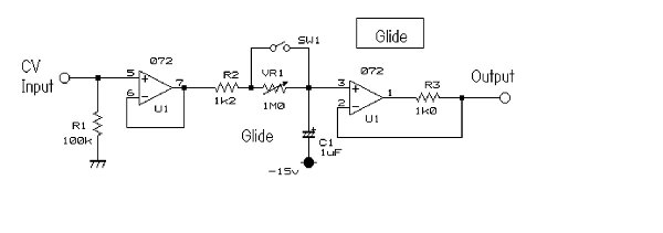
Hi guys.
The one below from Osamu Hoshuyamas "lunchbox synth" has worked well for me. It's buffered with voltage followers both on input and output, and is non-inverting. R2 doesn't have to be 1K2. 1K is fine. I didn't wire up or test the switch, but it looks useful. 
cheers,
Dave
(edited because *ahem* I just checked, and the lockbox synth is a Scott Bernadi synth, Sam's is a lunchbox modular.... Oh well....it was a nice day when I posted, I had a beer ...
Glad the circuit was of use to you Creekree - it was my first ever perfboard circuit, used to fix up a paia midi2CV8's CV zipper noise, which it did nicely using a 62K resistor instead of a 1M pot... )
| Description: |
|
| Filesize: |
86.24 KB |
| Viewed: |
1199 Time(s) |
| This image has been reduced to fit the page. Click on it to enlarge. |
|
Last edited by Dave Kendall on Fri Jul 03, 2009 4:51 pm; edited 1 time in total |
|
|
Back to top
|
|
|
creekree

Joined: Mar 30, 2006
Posts: 192
Location: Morgenland Neukölln
Audio files: 1
|
| Posted: Fri Jul 03, 2009 12:24 pm Post subject:
|
|
|
Dave,
thanks for posting that.
I quickly soldered it on stripboard - works like a charm!
Chris |
|
|
Back to top
|
|
|
j.dilisio
Joined: May 19, 2009
Posts: 200
Location: baltimore
|
| Posted: Sat Jul 18, 2009 2:54 pm Post subject:
|
|
|
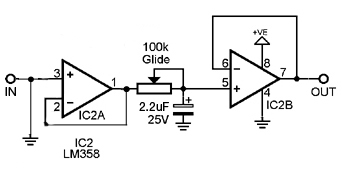
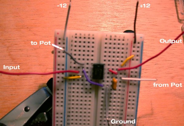
I'm having a little trouble getting this to work.
The CV signal I'm feeding it ranges between .5 and 3 volts.
The output from the first op-amp(pin1) is around 10.8V and stays around there for the rest of the path so the output frequency is really high.
I figure there's either something wrong with both of the LM358's I've tried,. or I've most likely made a really dumb mistake with the wiring.
I've attached a picture of the breadboard.
Any suggestions?
| Description: |
|
| Filesize: |
33.88 KB |
| Viewed: |
40019 Time(s) |

|
| Description: |
|
| Filesize: |
329.93 KB |
| Viewed: |
533 Time(s) |
| This image has been reduced to fit the page. Click on it to enlarge. |
|
|
|
|
Back to top
|
|
|
haxster
Joined: Feb 01, 2006
Posts: 246
Location: MONTEREY PARK, CA 91754
G2 patch files: 2
|
| Posted: Sat Jul 18, 2009 6:23 pm Post subject:
|
|
|
| From looking at the schematic above, you have the inversions wrong. (-)inv should be pin 2, pin 3 is (+)non-inv. Op-amp (B) has the same label error. Also you do not have a freedback resistor or jumper on Op-amp (A). |
|
|
Back to top
|
|
|
Tim Servo
Joined: Jul 16, 2006
Posts: 924
Location: Silicon Valley
Audio files: 11
|
| Posted: Sat Jul 18, 2009 6:28 pm Post subject:
Simple Glide/Slew/Lag/Portamento.. |
|
|
Whoops, you've got that first op-amp wired as a comparator. When the input goes just a teeny bit above or below ground, the output will jump between (about) +12 and -12V. No in between for the output of a comparator. If you look at the diagram above, you'll see there's a feedback path on the op amps from the output back to the "-" input. What you want is to have the first op-amp wired as a buffer or "voltage follower."
Tim (just a bit above ground) Servo |
|
|
Back to top
|
|
|
j.dilisio
Joined: May 19, 2009
Posts: 200
Location: baltimore
|
| Posted: Sat Jul 18, 2009 7:43 pm Post subject:
|
|
|
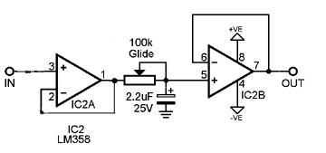
Thanks for replying so quickly!
It looks like I forgot to switch the + and - when I switched the numbers on the first op-amp. The second one should already be correct.
So all I'm missing is the feedback jumper.
Which of the following two schematics is right?
Does the jumper always go back to the - or whichever is the input?
| Description: |
|
| Filesize: |
34.67 KB |
| Viewed: |
39971 Time(s) |
|
| Description: |
|
| Filesize: |
34.96 KB |
| Viewed: |
39972 Time(s) |
|
| Description: |
|
| Filesize: |
87.13 KB |
| Viewed: |
581 Time(s) |
| This image has been reduced to fit the page. Click on it to enlarge. |
|
|
|
|
Back to top
|
|
|
j.dilisio
Joined: May 19, 2009
Posts: 200
Location: baltimore
|
| Posted: Sat Jul 18, 2009 7:47 pm Post subject:
|
|
|
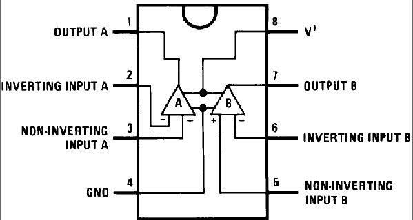
I just noticed that pin 4 is marked as ground on the data sheet.
Should I go by that or does it matter? |
|
|
Back to top
|
|
|
j.dilisio
Joined: May 19, 2009
Posts: 200
Location: baltimore
|
|
|
Back to top
|
|
|
Tim Servo
Joined: Jul 16, 2006
Posts: 924
Location: Silicon Valley
Audio files: 11
|
| Posted: Sat Jul 18, 2009 8:58 pm Post subject:
Simple Glide/Slew/Lag/Portamento.. |
|
|
Okay, good work, you're really close now. What you need to do is remove that connection to ground on the + input of the first op-amp. My guess is that's what causing the glide circuit to load down whatever is hooked to its input and mess up the output. Also, the LM358 can be powered by +V and Ground or +V and -V. My choice would be +V and -V (or "bipolar supplies") because then the glide circuit will be able to process any negative CVs that come its way.
Tim (wasn't there a dance named "The Glide"?) Servo |
|
|
Back to top
|
|
|
j.dilisio
Joined: May 19, 2009
Posts: 200
Location: baltimore
|
|
|
Back to top
|
|
|
LetterBeacon
Joined: Mar 18, 2008
Posts: 454
Location: London, UK
|
| Posted: Wed Oct 07, 2009 12:26 pm Post subject:
|
|
|
I'm thinking about building that circuit above - when the Glide pot is turned completely CCW, does that mean there is a 0 amount of glide, or is there still a little bit of glide going on?
Thanks! |
|
|
Back to top
|
|
|
j.dilisio
Joined: May 19, 2009
Posts: 200
Location: baltimore
|
| Posted: Wed Oct 07, 2009 2:24 pm Post subject:
|
|
|
| LetterBeacon wrote: | I'm thinking about building that circuit above - when the Glide pot is turned completely CCW, does that mean there is a 0 amount of glide, or is there still a little bit of glide going on?
Thanks! |
There's no glide when the pot is all the way down.
There's also a dual glide board available from Bridechamber for cheap, $2 i think.
_________________
DRONEGOAT |
|
|
Back to top
|
|
|
|

 Forum index » DIY Hardware and Software