| Author |
Message |
Sound
Joined: Jun 06, 2006
Posts: 842
Audio files: 1
|
 Posted: Fri Jul 30, 2010 4:24 pm Post subject: Posted: Fri Jul 30, 2010 4:24 pm Post subject:
|
  |
|
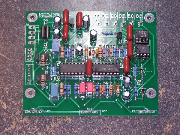
Hi Les, last week arrived the PCBs, Thanks!  |
|
|
Back to top
|
|
 |
Inventor
Stream Operator

Joined: Oct 13, 2007
Posts: 6221
Location: near Austin, Tx, USA
Audio files: 267
|
| Posted: Sat Jul 31, 2010 8:23 am Post subject:
|
|
|
| Sound wrote: | | Hi Les, last week arrived the PCBs, Thanks! |
Cool man, happy building!
Les
_________________
"Let's make noise for peace." - Kijjaz |
|
|
Back to top
|
|
|
kkissinger

Joined: Mar 28, 2006
Posts: 1356
Location: Kansas City, Mo USA
Audio files: 42
|
| Posted: Mon Aug 02, 2010 9:58 am Post subject:
A few questions |
|
|
Hi Les! Well, I've ordered all the parts and look forward to building this.
A couple of questions:
What does the STIM input do? I presume that I will connect it to a jack to send a signal to it. Is this correct? Would this work a little like sync?
Edit: found the answer on your Echuck page... thanks!
Speaking of sync, is the VCO syncable? Or does the STIM take care of this. (minor issue, just curious!)
How is the Feedback Send and Recieve best connected? Does it require a switch or can I route this through a pot for variable feedback?
Edit: found the answer on you Echuck page (route through a pot).
I'm designing the front panel layout now... very excited to get this up and running!
_________________
-- Kevin
http://kevinkissinger.com |
|
|
Back to top
|
|
|
wmonk
Joined: Sep 15, 2008
Posts: 528
Location: Enschede, the Netherlands
Audio files: 15
|
| Posted: Mon Aug 02, 2010 11:39 am Post subject:
Re: A few questions |
|
|
| kkissinger wrote: |
I'm designing the front panel layout now... very excited to get this up and running! |
Nice!
On my KS7 panel, I named the STIM input TRIGGER, as that is what it needs for a guitar like sound.
http://www.flickr.com/photos/woodymonk/4411881237/
For the VCO and VCF CV inputs. If you want to add a attenuator knob for a cv level, I suggest doing that for the VCF. But perhaps FMing the VCO gives interesting results.
_________________
Weblog! |
|
|
Back to top
|
|
|
kkissinger
Joined: Mar 28, 2006
Posts: 1356
Location: Kansas City, Mo USA
Audio files: 42
|
| Posted: Mon Aug 02, 2010 11:55 am Post subject:
Re: A few questions |
|
|
| wmonk wrote: | | kkissinger wrote: |
I'm designing the front panel layout now... very excited to get this up and running! |
Nice!
On my KS7 panel, I named the STIM input TRIGGER, as that is what it needs for a guitar like sound.
http://www.flickr.com/photos/woodymonk/4411881237/
For the VCO and VCF CV inputs. If you want to add a attenuator knob for a cv level, I suggest doing that for the VCF. But perhaps FMing the VCO gives interesting results. |
Thank you for the info.
Thus far, my front panel will have:
Coarse VCO frequency pot
Fine VCO frequency pot
VCO FM attenuator pot
VCF frequency pot
VCF FM attenuator pot
Feedback pot
STIM attenuator pot (possible, not sure about this)
3 VCO FM jacks (one attenuated)
3 VCF FM jacks (one attenuated)
1 Stim input jack
1 Output jack
I will simply sum the additional CV inputs via 100K resistors.
I presume that R13 is the volts/octave trim.
_________________
-- Kevin
http://kevinkissinger.com |
|
|
Back to top
|
|
|
wmonk
Joined: Sep 15, 2008
Posts: 528
Location: Enschede, the Netherlands
Audio files: 15
|
| Posted: Mon Aug 02, 2010 12:41 pm Post subject:
Re: A few questions |
|
|
| kkissinger wrote: |
I will simply sum the additional CV inputs via 100K resistors.
I presume that R13 is the volts/octave trim. |
It is! 
_________________
Weblog! |
|
|
Back to top
|
|
|
kkissinger
Joined: Mar 28, 2006
Posts: 1356
Location: Kansas City, Mo USA
Audio files: 42
|
|
|
Back to top
|
|
|
DGTom

Joined: Dec 08, 2008
Posts: 211
Location: Adelaide
Audio files: 3
G2 patch files: 1
|
| Posted: Fri Aug 06, 2010 3:05 am Post subject:
|
|
|
Can't wait to see your (assume it will be Aries) panel Kevin, love the aesthetics of your system.
I just wanted to say a MASSIVE thanks to Les. Last week (just before my computers all decided to die in one way or another) I got a surprise package in the mail; it was the updated version of the KS board 
Totally unexpected & the new board looks really good... as soon as I can afford to place an order with smallbear for the BBDs I'll be cracking on with both, but, I have alot of reading to catch up on first!
You guys rock!! |
|
|
Back to top
|
|
|
Inventor
Stream Operator
Joined: Oct 13, 2007
Posts: 6221
Location: near Austin, Tx, USA
Audio files: 267
|
| Posted: Fri Aug 06, 2010 6:35 am Post subject:
|
|
|
Thanks everyone, I'm really happy how things turned out so far. The only problem is the middle power supply connector appears to be reversed.
| Quote: | | Speaking of sync, is the VCO syncable? Or does the STIM take care of this. (minor issue, just curious!) |
The VCO runs pretty fast to get the clocking right on the BBD, so there is really no reason to sync it, and you can't do that anyway with this circuit. The VCO is a free-running oscillator without sync.
Also the aux connection was opened up in case anyone wants to add effects or muck with the feedback loop at all. I just short it with a jumper wire. You can use a pot too, I don't think it will matter that much.
Glad to see your build going so well, Kevin - and can't wait to hear your new module in action!
Les
_________________
"Let's make noise for peace." - Kijjaz |
|
|
Back to top
|
|
|
jeff-o
Joined: Jul 19, 2009
Posts: 97
Location: Ontario, Canada
|
| Posted: Fri Aug 06, 2010 6:47 am Post subject:
|
|
|
| Inventor wrote: | Thanks everyone, I'm really happy how things turned out so far. The only problem is the middle power supply connector appears to be reversed.
| Quote: | | Speaking of sync, is the VCO syncable? Or does the STIM take care of this. (minor issue, just curious!) |
The VCO runs pretty fast to get the clocking right on the BBD, so there is really no reason to sync it, and you can't do that anyway with this circuit. The VCO is a free-running oscillator without sync.
Also the aux connection was opened up in case anyone wants to add effects or muck with the feedback loop at all. I just short it with a jumper wire. You can use a pot too, I don't think it will matter that much.
Glad to see your build going so well, Kevin - and can't wait to hear your new module in action!
Les |
That's what I did with the feedback loop - I just shorted the two connectors together with a wire. It works fine! There doesn't seem to be any reason to add a simple pot in there to control the feedback (there's already a separate control for that!) but it could be useful for adding another filter of some sort... |
|
|
Back to top
|
|
|
kkissinger
Joined: Mar 28, 2006
Posts: 1356
Location: Kansas City, Mo USA
Audio files: 42
|
| Posted: Fri Aug 06, 2010 7:11 am Post subject:
|
|
|
| Inventor wrote: | | Thanks everyone, I'm really happy how things turned out so far. The only problem is the middle power supply connector appears to be reversed. |
Thank you for the heads-up. I'll watch for this.
I just noticed that I didn't use tempcos for the 2K resistors -- I'll go ahead with what I have and order tempcos.
I'm just going to make R34 a front panel control.
Very excited to get this up and running -- hard to concentrate on work!
_________________
-- Kevin
http://kevinkissinger.com |
|
|
Back to top
|
|
|
kkissinger
Joined: Mar 28, 2006
Posts: 1356
Location: Kansas City, Mo USA
Audio files: 42
|
| Posted: Sun Aug 08, 2010 5:27 pm Post subject:
|
|
|
Well, it kinda worked (but not to spec) when I first powered it up. However, I managed to hit something that I shouldn't have while troubleshooting and fried the BBD chip! Well, I only ordered one but managed to order some more (I found a decent price on them) and hope to be on track with this in a few days.
Here are the issues I've encountered:
1) the pitch only sweeps through less than one octave.
The op amp reduces the 30 volt sweep (from the front panel frequency control) down to about a 1 volt sweep (is this correct?)
The trimmer has no effect on the voltage -- I'm not sure why this doesn't work... perhaps the trimmer is defective. However, the filter's Voltage trimmer doesn't seem to make any difference either.
2) The VCO's frequency is around 500Khz -- is this correct? The VCO puts out a triangle wave that gets squared up by the time it passes through the Level Shifter (JLS).
3) The clock chip appears to divide the VCO's frequency by two. Is this correct?
4) (while my BBD was working) the device would self-oscillate at high feedback settings. I presume this is normal.
5) When giving a short pulse as a stim (trigger), I got a short "pluck" out of the sound but not the long decay that I expect. Perhaps I need to use a different BBD chip? I believe the one I had was a vintage model.
The filter worked at first -- however doesn't work now -- perhaps it has no audible effect without a working BBD chip. Note that the only way I can get output is from the STIM signal -- without a BBD this isn't any other signal at the output (of course).
Forgive all the questions -- I've not worked with BBD devices before so I'm kind of trying to figure out what to look for here.
Oh... the control voltage for the VCO appears to be clamped down to a low range. Could the zeners or the 1N4148s be involved in this?
All the voltages -- +15, -15, and +5 all look good.
Any help/advice appreciated... thanks!
_________________
-- Kevin
http://kevinkissinger.com |
|
|
Back to top
|
|
|
Inventor
Stream Operator
Joined: Oct 13, 2007
Posts: 6221
Location: near Austin, Tx, USA
Audio files: 267
|
| Posted: Sun Aug 08, 2010 10:08 pm Post subject:
|
|
|
| kkissinger wrote: | | Well, it kinda worked (but not to spec) when I first powered it up. However, I managed to hit something that I shouldn't have while troubleshooting and fried the BBD chip! Well, I only ordered one but managed to order some more (I found a decent price on them) and hope to be on track with this in a few days. |
Kevin, glad to hear you got some sounds before the bbd chip gave up it's smoke and you'll be back in action as soon as you get new chips. Also thanks for taking the time to share your experiences with us here. I'll answer all of your items one at a time.
| Quote: |
Here are the issues I've encountered:
1) the pitch only sweeps through less than one octave.
The op amp reduces the 30 volt sweep (from the front panel frequency control) down to about a 1 volt sweep (is this correct?)
The trimmer has no effect on the voltage -- I'm not sure why this doesn't work... perhaps the trimmer is defective. However, the filter's Voltage trimmer doesn't seem to make any difference either.
|
Yes, I knew I should have documented the correct resistor values that control the sweep range. The published value of 14.3k (IIRC) is for 9V battery operation which is my situation in my lab, but not yours Kevin. The circuit is designed to have 27k resistors there at R27 and R32 with a supply voltage of 15V. So just replace R27 and R32 with 27k resistors or closest value and you'll get better range from both the VCO and the VCF. My apologies for not documenting this in this development thread.
| Quote: |
2) The VCO's frequency is around 500Khz -- is this correct? The VCO puts out a triangle wave that gets squared up by the time it passes through the Level Shifter (JLS).
|
The VCO should vary from somewhere in the ballpark of 10 or 20 kHz up to 200 or 400 kHz or something like that. I never characterized it, I just ballparked it and it worked fine in all my prototypes. Maybe I shouldn't but instead of being all methodical when I design, I tend to just wing it lots of the time. Works ok most of the time, lol.
| Quote: |
3) The clock chip appears to divide the VCO's frequency by two. Is this correct?
|
Yes, correct. It does this with a D flip-flop wired into a T flip-flop and it outputs a two-phase clock. tick tock.
| Quote: |
4) (while my BBD was working) the device would self-oscillate at high feedback settings. I presume this is normal.
|
Yes it's intentional and it sounds really cool to me, especially if you keep the feedback pot between 40% and 60% settings. It's a bit of a hair trigger and perhaps that needs to be widened to the full range of the pot. Anyway, the clamp & bias circuit happily turned out to actually do a bit of a tube-like rounding of the feedback saturation waveforms, with rounded tops and bottoms to the oscillation. It's no tube amp but it does sound "warm" to me.
| Quote: |
5) When giving a short pulse as a stim (trigger), I got a short "pluck" out of the sound but not the long decay that I expect. Perhaps I need to use a different BBD chip? I believe the one I had was a vintage model.
|
The 256 vintage obsolete chip is best for percussion and lead guitar plucks, the 1024 chip produces great midrange and bass guitar sounds, and the 2048 chip is really bassy at all settings. For percussion try a 256 chip or maybe a 1024 chip. If I had to choose one chip it would be the 1024 chip for the widest range of sounds available.
Back to the point, you'll get the best sustain from your stim pulse by adjusting the feedback pot to ever so slightly below the feedback saturation point, which is around 50% position or so. BBD chips with more stages produce more sustain for guitar and synth sounds.
| Quote: |
The filter worked at first -- however doesn't work now -- perhaps it has no audible effect without a working BBD chip. Note that the only way I can get output is from the STIM signal -- without a BBD this isn't any other signal at the output (of course).
|
Yeah nothing works without that BBD chip. 
| Quote: |
Forgive all the questions -- I've not worked with BBD devices before so I'm kind of trying to figure out what to look for here.
Oh... the control voltage for the VCO appears to be clamped down to a low range. Could the zeners or the 1N4148s be involved in this?
All the voltages -- +15, -15, and +5 all look good.
Any help/advice appreciated... thanks! |
The control voltage is low because of the resistor value issue described above, I think anyway.
Conclusion: change the two resistors and plug in a 1024 BBD chip and you should be good to go, Kevin. Best of luck and we're looking forward to an mp3!
Les
_________________
"Let's make noise for peace." - Kijjaz |
|
|
Back to top
|
|
|
kkissinger
Joined: Mar 28, 2006
Posts: 1356
Location: Kansas City, Mo USA
Audio files: 42
|
| Posted: Sun Aug 08, 2010 10:58 pm Post subject:
|
|
|
Thank you for all the info! Much appreciated. I can go ahead and replace the resistors you mentioned and can put a frequency counter on the vco to determine its range.
I just checked -- I am using the MN3207 BBD -- the 1024 chip that you suggested. I have some more on order.
I will keep you posted. 
_________________
-- Kevin
http://kevinkissinger.com |
|
|
Back to top
|
|
|
kkissinger
Joined: Mar 28, 2006
Posts: 1356
Location: Kansas City, Mo USA
Audio files: 42
|
| Posted: Wed Aug 11, 2010 8:31 am Post subject:
|
|
|
| kkissinger wrote: | | Thank you for all the info! Much appreciated. I can go ahead and replace the resistors you mentioned and can put a frequency counter on the vco to determine its range. |
Well, my replacement BBD should arrive any day now. In the meantime, I replaced R27 however I am still not getting a significant frequency modulation from the VCO.
btw -- I think I've figured out the math here -- the VCO runs around 500khz, the clock chip cuts it in half to 250khz, since the BBD has 1028 steps the period would be around 243 hz -- just a little lower than middle 'C' (256 hz). This would correspond with the result I got before I fried my BBD. Incidentally, this would explain (if I am understanding this correctly) that a 2056 BBD would drop the pitch an additional octave -- down to 121.5 hz.
Well, I'm still learning about the 13700 OTA -- it is configured as a current-controlled oscillator -- which would explain the increase to R27 since I'm running on +/- 15v instead of 9v.
However, I still don't get much of a swing and am wondering if an adjustment to R26 and/or R23 is needed, too. Any thoughts on that?
Since IC2A has a 2k negative feedback resistor it greatly attenuates the input voltage swing -- and R13 (the 100 ohm trimmer) only works across 20% of that (because it is in series with R23). This would explain why I see very little amplitude change when adjusting R13.
Having said this, I am scrutinizing the value of R26 -- perhaps it needs to be increased, too (say to around 200K ??).
Also, I want to be sure that my expectations are correct -- can I expect this to sweep through a range of say, 5 or six octaves? In order to do this, the VCO's high frequency would need to be 2^5 times the lowest frequency. Is this a reasonable expectation for this circuit?
Oh... you already answered this:
| Quote: | | The VCO should vary from somewhere in the ballpark of 10 or 20 kHz up to 200 or 400 kHz or something like that. |
Thus, my VCO is running at the high end of the range but I can't slow it down.
Thanks for your help -- while I'm a reasonably experienced DIYr I am, compared to an electrical engineer, a tinkerer. Thanks for bearing with me!
Edit: a few more questions --
I am also scrutinizing the resistors in the oscillator's feedback loop -- R14 in particular (since it connects to Vee) -- but perhaps R11 and R12 need tweeks, too.
I think we are on the right track... that some adjustments need to be made for +/- 15v operation.
_________________
-- Kevin
http://kevinkissinger.com |
|
|
Back to top
|
|
|
jeff-o
Joined: Jul 19, 2009
Posts: 97
Location: Ontario, Canada
|
| Posted: Wed Aug 11, 2010 9:07 am Post subject:
|
|
|
I think you can expect a range of just over 3 octaves, maximum. The reason for this is that the BBD device (MN3208, for example) is capable of a delay of 10mS to 100mS. So if you do the math, 100 is 3.3 (ish) octaves above 10. Of course, when you convert from a period to a frequency the result is the same.
If you'd like me to take some measurements on my board, I'll see if I can find some time. Just let me know what you're measuring so I can duplicate what you're doing. Note that I'm running my board at +/-9V. |
|
|
Back to top
|
|
|
kkissinger
Joined: Mar 28, 2006
Posts: 1356
Location: Kansas City, Mo USA
Audio files: 42
|
| Posted: Wed Aug 11, 2010 9:54 am Post subject:
|
|
|
| jeff-o wrote: | | If you'd like me to take some measurements on my board, I'll see if I can find some time. Just let me know what you're measuring so I can duplicate what you're doing. Note that I'm running my board at +/-9V. |
Jeff, thank you for the info. If I can't get this to work, I will take you up on some measurements.
I'm at the office at the moment -- I'm considering a change to R14 from 5.1K to around 35K to compensate for Vee. My guess is that the bias is around -8.05v at the junction of R14/R11 with a -9v supply. My guess is that to substitute a larger value -- around 35K will compensate for the -15v supply and bring the bias close to -8v.
... at least, it is something to try!
_________________
-- Kevin
http://kevinkissinger.com |
|
|
Back to top
|
|
|
Inventor
Stream Operator
Joined: Oct 13, 2007
Posts: 6221
Location: near Austin, Tx, USA
Audio files: 267
|
| Posted: Thu Aug 12, 2010 5:46 am Post subject:
|
|
|
OK, first let me apologize for not testing the board at 15V or 12V supply voltages. I have no power supply and no cash to buy one with or build one at this time, but I really should have tried to set something up for this.
I believe that R14 is fine as it is for a 15V supply since it is merely a pull-down resistor for the output buffer transistors. R11, however, could be the source of the problem. R11 controls the amplitude of the triangular output waveform of the VCO, and we may need a larger amplitude for a 15V supply. So what I'd suggest is wiring a 100k or 1M pot in for R11 and watching the VCO (TP14) output waveform on a scope while adjusting the pot. It may also be a good idea to observe the output clock of the BBD clocking chip (MN3902) to see if it is stable at all VCO input voltages.
Again, sorry for any inconvenience and I hope we can get to the bottom of this really soon. Thanks for your time, Jeff and Kevin.
Les
_________________
"Let's make noise for peace." - Kijjaz |
|
|
Back to top
|
|
|
kkissinger
Joined: Mar 28, 2006
Posts: 1356
Location: Kansas City, Mo USA
Audio files: 42
|
| Posted: Thu Aug 12, 2010 6:30 am Post subject:
|
|
|
| Inventor wrote: | OK, first let me apologize for not testing the board at 15V or 12V supply voltages. I have no power supply and no cash to buy one with or build one at this time, but I really should have tried to set something up for this.
I believe that R14 is fine as it is for a 15V supply since it is merely a pull-down resistor for the output buffer transistors. R11, however, could be the source of the problem. R11 controls the amplitude of the triangular output waveform of the VCO, and we may need a larger amplitude for a 15V supply. So what I'd suggest is wiring a 100k or 1M pot in for R11 and watching the VCO (TP14) output waveform on a scope while adjusting the pot. It may also be a good idea to observe the output clock of the BBD clocking chip (MN3902) to see if it is stable at all VCO input voltages.
Again, sorry for any inconvenience and I hope we can get to the bottom of this really soon. Thanks for your time, Jeff and Kevin.
Les |
The main problem is that the VCO frequency is "stuck" at the high end and, regardless of the control-voltage value, the frequency won't change.
The triangle wave and the subsequent square wave at JLS look good -- 5v peak-to-peak.
At this point, I suspect the problem is with some of the resistor values in the VCO circuit -- the expo converter may be working to spec but I'm unsure as to what voltages should come out of it.
Jeff, it would be useful to know the voltage swing that you get at Test Point OCC -- that is, when you vary the front-panel frequency control from low to high, I'd like to know what your voltages at OCC are. (I see a voltage swing of < 1volt.)
Thanks!
_________________
-- Kevin
http://kevinkissinger.com |
|
|
Back to top
|
|
|
jeff-o
Joined: Jul 19, 2009
Posts: 97
Location: Ontario, Canada
|
| Posted: Thu Aug 12, 2010 6:59 am Post subject:
|
|
|
| kkissinger wrote: | The main problem is that the VCO frequency is "stuck" at the high end and, regardless of the control-voltage value, the frequency won't change.
The triangle wave and the subsequent square wave at JLS look good -- 5v peak-to-peak.
At this point, I suspect the problem is with some of the resistor values in the VCO circuit -- the expo converter may be working to spec but I'm unsure as to what voltages should come out of it.
Jeff, it would be useful to know the voltage swing that you get at Test Point OCC -- that is, when you vary the front-panel frequency control from low to high, I'd like to know what your voltages at OCC are. (I see a voltage swing of < 1volt.)
Thanks! |
I can tell you for sure that the VCO frequency does change properly, though to what degree I don't know. Unless someone beats me to it, I'll get that measurement for you tonight. |
|
|
Back to top
|
|
|
jeff-o
Joined: Jul 19, 2009
Posts: 97
Location: Ontario, Canada
|
| Posted: Thu Aug 12, 2010 8:17 pm Post subject:
|
|
|
| OK! On my KS board, OCC swings from -3.50V to -6.15V with respect to ground. |
|
|
Back to top
|
|
|
jeff-o
Joined: Jul 19, 2009
Posts: 97
Location: Ontario, Canada
|
| Posted: Thu Aug 12, 2010 8:24 pm Post subject:
|
|
|
| Scratch that, my batteries were low. On fresh batteries, the swing is from -4.32V to -8.13V. |
|
|
Back to top
|
|
|
kkissinger
Joined: Mar 28, 2006
Posts: 1356
Location: Kansas City, Mo USA
Audio files: 42
|
| Posted: Thu Aug 12, 2010 10:56 pm Post subject:
|
|
|
| jeff-o wrote: | | Scratch that, my batteries were low. On fresh batteries, the swing is from -4.32V to -8.13V. |
Thank you for the info. Since my OCC voltage swing is less than 1 volt, then I need to focus on the Input op amp and expo converter.
Note that I get the same voltage swing on the VCF side -- so I don't suspect a bad component but rather, some resistor values tha must be changed.
_________________
-- Kevin
http://kevinkissinger.com |
|
|
Back to top
|
|
|
jeff-o
Joined: Jul 19, 2009
Posts: 97
Location: Ontario, Canada
|
| Posted: Fri Aug 13, 2010 7:06 am Post subject:
|
|
|
| kkissinger wrote: | | jeff-o wrote: | | Scratch that, my batteries were low. On fresh batteries, the swing is from -4.32V to -8.13V. |
Thank you for the info. Since my OCC voltage swing is less than 1 volt, then I need to focus on the Input op amp and expo converter.
Note that I get the same voltage swing on the VCF side -- so I don't suspect a bad component but rather, some resistor values tha must be changed. |
I can't imagine that it's the operating voltage. My old batteries were running at about 7.5V, and all that did was reduce the swing proportionally. If you're running at 15V, I'd expect the swing to be larger. I suspect that something is connected up wrong. Have you checked everything to make sure it's installed properly? |
|
|
Back to top
|
|
|
kkissinger
Joined: Mar 28, 2006
Posts: 1356
Location: Kansas City, Mo USA
Audio files: 42
|
| Posted: Fri Aug 13, 2010 8:41 am Post subject:
|
|
|
| jeff-o wrote: | | If you're running at 15V, I'd expect the swing to be larger. |
Jeff, if you have a chance, I would appreciate knowing what your voltage swing is at OCV.
The op-amp greatly attenuates the input voltage and I will start from there.
As you mentioned, my voltage swings should be proportional to yours.
| jeff-o wrote: | | I suspect that something is connected up wrong. Have you checked everything to make sure it's installed properly? |
Well, of course something isn't correct -- could be a cold/weak solder joint, a bad component, or perhaps something microscopic (a break in a trace or an undetected solder bridge). The transistors could be leaky -- basically, if I can find what is pulling down the voltage from IC2 then I should be on the road to fixing this. Your measurements provide baseline values which will contribute greatly to a solution.
Thanks again!
_________________
-- Kevin
http://kevinkissinger.com |
|
|
Back to top
|
|
|
|

 Forum index » DIY Hardware and Software » Les Hall's Projects including eChucK