| Author |
Message |
haricots

Joined: Aug 15, 2007
Posts: 33
Location: guelph
|
 Posted: Thu Mar 11, 2010 12:36 pm Post subject: Posted: Thu Mar 11, 2010 12:36 pm Post subject:
 S&H/Noise module - S&H not so functional anymore S&H/Noise module - S&H not so functional anymore |
  |
|
Sometime last year I completed the S&H/Noise module (Bridechamber kit). It's been working great up until now. The S&H output seems really 'low' - as in I'm not getting much modulation out of it. It's outputting but very weakly. Everything else works fine (like the noise outputs, random). Any ideas where I should start looking? I can build kits but can't troubleshoot worth a damn.  |
|
|
Back to top
|
|
 |
yusynth

Joined: Nov 24, 2005
Posts: 1314
Location: France
|
| Posted: Fri Mar 12, 2010 12:17 am Post subject:
|
|
|
Is it clocking normally ?
Try to replace U2, the TL074, one of its AOP may have died.
_________________
Yves |
|
|
Back to top
|
|
|
haricots
Joined: Aug 15, 2007
Posts: 33
Location: guelph
|
| Posted: Fri Mar 12, 2010 8:53 am Post subject:
|
|
|
| Upon further inspection, I think the cv out is ok 'strength'-wise, but the range is in the low end of the spectrum which makes the modulation pretty rumbly. Does this make sense? |
|
|
Back to top
|
|
|
yusynth
Joined: Nov 24, 2005
Posts: 1314
Location: France
|
| Posted: Sat Mar 13, 2010 7:17 am Post subject:
|
|
|
I dont understand your explainations can you develop ?
Can you describe the patch your are using and the potentiometer settings ?
_________________
Yves |
|
|
Back to top
|
|
|
haricots
Joined: Aug 15, 2007
Posts: 33
Location: guelph
|
| Posted: Sun Mar 14, 2010 5:43 pm Post subject:
|
|
|
Sorry for my horrible explanation. What I have noticed is that if i invert the signal it is at least in the usable range. When the S&H output is used without inversion the range of the modulations is too low to be usable (like it is pitched very low). Even inverted it doesn't give that nice syncopated change that you would expect with a clocked S&H. Maybe the glide circuit is somehow messed up? It is so hard to tell let alone explain what is going on here.
Here is my patch > vco with standard cv in, outputted to a vca. s&h module with clock in from a pulse divider (/2). s&h output to the vco expo cv in. nothing but low register rumbles. If I invert the signal it is within a usable range but still sounds 'off' to my ears. Strange as it has worked flawlessly up until now. |
|
|
Back to top
|
|
|
yusynth
Joined: Nov 24, 2005
Posts: 1314
Location: France
|
| Posted: Mon Mar 15, 2010 1:47 pm Post subject:
|
|
|
| haricots wrote: | Sorry for my horrible explanation. What I have noticed is that if i invert the signal it is at least in the usable range. When the S&H output is used without inversion the range of the modulations is too low to be usable (like it is pitched very low). Even inverted it doesn't give that nice syncopated change that you would expect with a clocked S&H. Maybe the glide circuit is somehow messed up? It is so hard to tell let alone explain what is going on here.
Here is my patch > vco with standard cv in, outputted to a vca. s&h module with clock in from a pulse divider (/2). s&h output to the vco expo cv in. nothing but low register rumbles. If I invert the signal it is within a usable range but still sounds 'off' to my ears. Strange as it has worked flawlessly up until now. |
What do you input in the S&H input ?
_________________
Yves |
|
|
Back to top
|
|
|
haricots
Joined: Aug 15, 2007
Posts: 33
Location: guelph
|
| Posted: Mon Mar 15, 2010 5:26 pm Post subject:
|
|
|
| Nothing in this case - it being hardwired to white noise. I've also tried manually patching in white and pink - same result. |
|
|
Back to top
|
|
|
Argitoth
Joined: Jun 24, 2008
Posts: 152
Location: Gilbert, Arizona
Audio files: 3
G2 patch files: 6
|
| Posted: Mon Sep 06, 2010 5:32 pm Post subject:
|
|
|
Alright, I now have Haricot's damaged yusynth module, now it's my turn to attempt to figure out the problem! hehe.
So, looks like there's a problem with the module... now I'm not even sure if I simply didn't notice it before or it suddenly stopped working. All I know is that the "output" is supposed to be a S&H out, but what comes out of it sounds as if it's AC-coupled. I get random-ampitude spikes instead up/down DC behavior that S&H is known for.
Should I replace TL074 or might you have a better idea with my new description of the problem? Thanks Yves! |
|
|
Back to top
|
|
|
Argitoth
Joined: Jun 24, 2008
Posts: 152
Location: Gilbert, Arizona
Audio files: 3
G2 patch files: 6
|
| Posted: Mon Sep 06, 2010 7:25 pm Post subject:
|
|
|
Looking at the PCB there are some cold solder joints. Also, I see flux all over the place as if the board was never washed. Isn't it supposed to be washed?
Audio demo of "output" going into a VCO FM and directly into audio path. http://www.elanhickler.com/misc/random-problem.flac
Is Flac OK? |
|
|
Back to top
|
|
|
yusynth
Joined: Nov 24, 2005
Posts: 1314
Location: France
|
| Posted: Tue Sep 07, 2010 5:23 am Post subject:
|
|
|
Hi Argitoth
I am on leave now and stuck in an airport because of a strike.
I'll get back to to you tomorrow when I will be returned home.
Cheers
_________________
Yves |
|
|
Back to top
|
|
|
Argitoth
Joined: Jun 24, 2008
Posts: 152
Location: Gilbert, Arizona
Audio files: 3
G2 patch files: 6
|
| Posted: Tue Sep 07, 2010 8:58 am Post subject:
|
|
|
| I fixed all the cold solder joints I could see, no improvement of behavior, but that's expected. Even a horrible soldering job is still good enough for a synth module to work. |
|
|
Back to top
|
|
|
yusynth
Joined: Nov 24, 2005
Posts: 1314
Location: France
|
| Posted: Wed Sep 08, 2010 2:58 am Post subject:
|
|
|
| Argitoth wrote: | | I fixed all the cold solder joints I could see, no improvement of behavior, but that's expected. Even a horrible soldering job is still good enough for a synth module to work. |
Heve you checked that the jumper (which makes it possible to select between linear or log mod) is present ?
Are the noise sources (white pink) working ? What is the output level (as sen with a scope, peak to peak ?).
From the audio file, either nothing is actually fed into the S&H either a component is dead, with the most probable suspect the BF245 JFET (preferably a BC245C), the S&H capacitor.
Have you an oscilloscope to check the signals : before the diode that drives the JFET grid, on the JFET grid, on the JFET source.
_________________
Yves |
|
|
Back to top
|
|
|
Argitoth
Joined: Jun 24, 2008
Posts: 152
Location: Gilbert, Arizona
Audio files: 3
G2 patch files: 6
|
| Posted: Wed Sep 08, 2010 5:50 am Post subject:
|
|
|
I don't have a scope. I want to at least get a multimeter soon...
Everything works. The nosie level outputs are good, the internal clock is solid. |
|
|
Back to top
|
|
|
yusynth
Joined: Nov 24, 2005
Posts: 1314
Location: France
|
| Posted: Thu Sep 09, 2010 6:44 am Post subject:
|
|
|
Without measurements it's difficult to figure out what's happening.
The simple things to try out are :
replace the TL074 of the S&H, if it does not solve the problem...
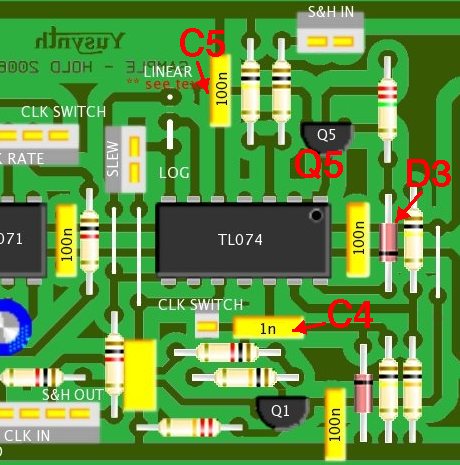
check that the diode D3 is healthy, (replace it if not)...
change the JFET Q5 (BF245C)...
change the C5 (100nF) capacitor
you may also increase the value of C4 up to 4.7nF as well.
_________________
Yves |
|
|
Back to top
|
|
|
Argitoth
Joined: Jun 24, 2008
Posts: 152
Location: Gilbert, Arizona
Audio files: 3
G2 patch files: 6
|
| Posted: Thu Sep 09, 2010 12:43 pm Post subject:
|
|
|
| I can't find anything documents that tell me where C5 and other parts are. I just see values. |
|
|
Back to top
|
|
|
drapdap

Joined: Oct 11, 2004
Posts: 204
Location: London
Audio files: 1
G2 patch files: 1
|
| Posted: Thu Sep 09, 2010 2:32 pm Post subject:
|
|
|
| Argitoth wrote: | | I can't find anything documents that tell me where C5 and other parts are. I just see values. |
http://yusynth.net/Modular/Commun/NOISE/NoiseSH-sch.jpg
So C5 is Drain of the Fet...
Odd, i built 3 of these, 1 not working with the same synthomps. no, pun intended.  so thanks to Yves for the leads, i thought it's a grounding issue... so thanks to Yves for the leads, i thought it's a grounding issue... |
|
|
Back to top
|
|
|
Argitoth
Joined: Jun 24, 2008
Posts: 152
Location: Gilbert, Arizona
Audio files: 3
G2 patch files: 6
|
| Posted: Thu Sep 09, 2010 2:46 pm Post subject:
|
|
|
Drapdad, are you saying you fixed it?
Sorry, I have a very hard time reading a schematic. Could you tell me what part the C5 capacitor and D3 is near? |
|
|
Back to top
|
|
|
yusynth
Joined: Nov 24, 2005
Posts: 1314
Location: France
|
|
|
Back to top
|
|
|
Argitoth
Joined: Jun 24, 2008
Posts: 152
Location: Gilbert, Arizona
Audio files: 3
G2 patch files: 6
|
| Posted: Fri Sep 10, 2010 7:49 am Post subject:
|
|
|
| By the way, is the lin/log on the board for slew type or is it something else? |
|
|
Back to top
|
|
|
yusynth
Joined: Nov 24, 2005
Posts: 1314
Location: France
|
| Posted: Fri Sep 10, 2010 8:05 am Post subject:
|
|
|
| Argitoth wrote: | | By the way, is the lin/log on the board for slew type or is it something else? |
Yes it concerns the slew type.
_________________
Yves |
|
|
Back to top
|
|
|
Argitoth
Joined: Jun 24, 2008
Posts: 152
Location: Gilbert, Arizona
Audio files: 3
G2 patch files: 6
|
| Posted: Fri Sep 10, 2010 8:18 am Post subject:
|
|
|
ah shoot, one question per post sorry...
Is it possible the access the slew limiter outside the S&H circuit by deriving some wires to sockets or something? |
|
|
Back to top
|
|
|
yusynth
Joined: Nov 24, 2005
Posts: 1314
Location: France
|
| Posted: Fri Sep 10, 2010 8:31 am Post subject:
|
|
|
You would have to cut a track
_________________
Yves |
|
|
Back to top
|
|
|
Argitoth
Joined: Jun 24, 2008
Posts: 152
Location: Gilbert, Arizona
Audio files: 3
G2 patch files: 6
|
| Posted: Fri Sep 10, 2010 8:41 am Post subject:
|
|
|
Alright, so there's an input and an output. So either there's two traces I need to cut to derive input and output from or maybe one or the other is derived from a wire already.
Could you show me!? |
|
|
Back to top
|
|
|
Argitoth
Joined: Jun 24, 2008
Posts: 152
Location: Gilbert, Arizona
Audio files: 3
G2 patch files: 6
|
| Posted: Fri Sep 10, 2010 10:44 am Post subject:
|
|
|
WHAT THE F...
Oh great, now my other Yusynth Random S&H half stopped working. The clock is dead. There's nothing coming out of "out."
So this is what happened. I plugged it in. I check outputs. "Oh good everythings working on my module that never had problems before." After a few minutes, the LED stops blinking "what the ****." I re-check outputs.
Now nothing. Noise still functions like it does on the other one. |
|
|
Back to top
|
|
|
yusynth
Joined: Nov 24, 2005
Posts: 1314
Location: France
|
| Posted: Fri Sep 10, 2010 12:04 pm Post subject:
|
|
|
Did you plug something special in it ?
If the clock stopped working you may have to replace the TL071 ?
_________________
Yves |
|
|
Back to top
|
|
|
|

 Forum index » DIY Hardware and Software » YuSynth