| Author |
Message |
Inventor
Stream Operator

Joined: Oct 13, 2007
Posts: 6221
Location: near Austin, Tx, USA
Audio files: 267
|
 Posted: Sun Apr 22, 2012 8:02 pm Post subject: Posted: Sun Apr 22, 2012 8:02 pm Post subject:
|
  |
|
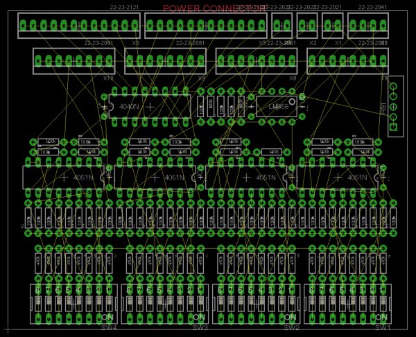
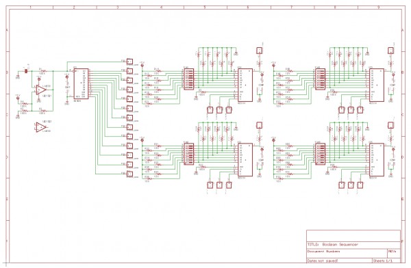
Alright, let's dive right into this creation! The board is extremely simple. I have not yet added power connectors and tempo potentiometer, and due to board space limitations there may be changes, however this is how it is at this time. See the schematic diagram below and don't focus on component values or details like that, we'll discuss those things later. Just look at the circuit topology.
On the left we have a binary counter in the CD4040 12 bit binary counter chip, clocked by a relaxation oscillator of fixed frequency. I will change the negative feedback resistor to a pot for the actual board, enabling the user to run the BS at a range of frequencies. It produces a 12 bit count and the clock itself is brought out as the 13th bit (LSB, or least significant bit). The output pins are driven straight into panel mounted banana jacks.
Yes that's right, banana jacks are best for this project because of all the usual reasons and primarily because they are stackable which is necessary here. The circuit board, shown in the diagram below the schematic is arranged so that the board functions as the front panel. I rather like this approach. You can put a plate or some conformal coating or something on it to protect the chips if you like, but the beauty of just stuffing a board ad there you have your panel is just too nice to resist. Of course, if you want a traditional panel you can arrange that too with a little tricky soldering to the giant panel mount banana jack holes.
The other subcircuit on the schematic is the LUT, or Look-Up Table. Also referred to as the Logic UniT, the LUT is basically an ANY gate. That is, by setting the 8 bit dip switch you can program the three input gate to be any logic function that you like. It's totally arbitrary and there are 256 possible gates including the trivial cases. You can make it an AND, NAND, OR, NOR, XOR, XNOR, or any other logic function you want. That's the beauty and the power of this ANY gate LUT thingie - it frees up the Boolean Sequencer logic block to be ANYTHING we want it to be! WOW! Thanks JingleJoe for sharing this in another post in the Lunetta forum. It really sparked my imagination.
Anyway that's the overview. more details tofollow.
Les
| Description: |
Boolean Sequencer Schematic Zoomed Out View
Do not read component values, just look at circuit topology. |
|
| Filesize: |
443.05 KB |
| Viewed: |
814 Time(s) |
| This image has been reduced to fit the page. Click on it to enlarge. |
|
| Description: |
Boolean Sequencer PCB Layout
I will probably reduce it to only three gates to accomodate other board features (to be discussed in the thread). |
|
| Filesize: |
917.81 KB |
| Viewed: |
656 Time(s) |
| This image has been reduced to fit the page. Click on it to enlarge. |
|
_________________
"Let's make noise for peace." - Kijjaz |
|
|
Back to top
|
|
 |
Inventor
Stream Operator
Joined: Oct 13, 2007
Posts: 6221
Location: near Austin, Tx, USA
Audio files: 267
|
| Posted: Sun Apr 22, 2012 8:16 pm Post subject:
|
|
|
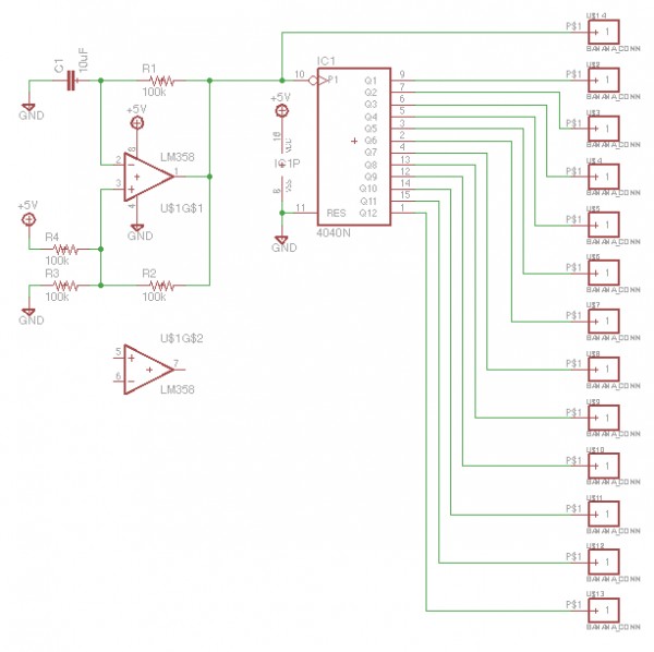
Next let's look at the two subcircuits. The boolean sequencer consists of a counter driven by a clock. The clock is simply a relaxation oscillator which has an exponential oscillation internally producing a square wave output with 50% duty cycle. It is biased up with artificial ground and uses one half of the LM358 dual opamp from www.sparkfun.com.
The counter is the classic CD4040 12 bit binary counter. Unlike the 4020 and 4060 companion counters, the 4040 uses all of the bits and the LSB of the 12 bit count is exactly twice the frequency of the clock. This means that we can tap the clock for a lucky 13th bit, giving us twice the sequence length.
Naturally we can make simple beats of 4, 8, 16, etc steps just by using the lower bits of the counter (or any close group of bits), or we can go up the ladder and have 32, 64, 128, 256, 512, 1024, 2048, 4096, or 8192 bits in the sequence. With the clock at some reasonable tempo rate such as 3 beats per second or 6 beats per second or whatever, 8192 steps will last the duration of a song or a long song without repeating.
I think it might be good to provide access via a banana jack to the reset pin so that one could use the logic to decode the output of the count and reset the count at any given value of the count. This feature would enable ANY sequence length at all (2, 3, 4, 5, 6, 7, 8, ... 8188, 8189, 8190, 8191, 8192). I rather like that as it makes the count truly flexible.
I need to add power connectors (duh), bypass caps, mounting holes (4-40), clock i/o and do something with the other opamp (Possibly a nice twangy filter or something cool like that).
Anyway, that's the counter section of the boolean sequencer board. Next: a discussion of the LUT.
Les
| Description: |
Boolean Sequencer Counter Subcircuit
Relaxation Oscillator and 12 bit counter forms a 13 bit count for 8192 step sequence maximum. |
|
| Filesize: |
143.03 KB |
| Viewed: |
704 Time(s) |
| This image has been reduced to fit the page. Click on it to enlarge. |
|
_________________
"Let's make noise for peace." - Kijjaz |
|
|
Back to top
|
|
|
Inventor
Stream Operator
Joined: Oct 13, 2007
Posts: 6221
Location: near Austin, Tx, USA
Audio files: 267
|
| Posted: Sun Apr 22, 2012 8:37 pm Post subject:
|
|
|
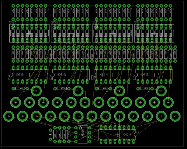
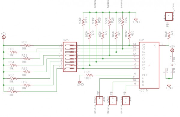
The LUT, of which there are curently four (you cannot have enough LUTs, lol), is an arbitrary three-input logic gate. You can program it to have any logic truth table that is possible which is basically 256 possible logic tables. This powerful feature enbles a tremendous amount of creativity in the music sequence that is produced, so enjoy it my friends! ! ! ! !
THe LUT is basically just an 8 bit MUX, or multiplexor. The three logic gate inputs select which of the eight inputs that gets applied to the output of the unit. Now that I think of it, this implementation will have an output impedance that is determined by the pull-up and pull-down resistor values, and I used 100k and 10k there, so I'd better either buffer them or use lower valued resistors, hmmm...
Anyway, there's not much to it. You set the logic function with the DIP switch (dual in-line package) and apply the inputs to the panel mount banana jacks and take the output from the panel mount banana jack. Simple enough, eh?
There is barely room for four LUTs and one counter on each board, which is enough for many sequences however just like the Karplus Strong boards, these simple, inexpensive, and easy to build little buggers go well in groups. By putting say three or four of them side by side, you can (when I add the daisy-chain feature, remind me) daisy chain the counters to produce a massive 100 years or more sequence length maximum. Dang.
Also as I mentioned you cannot have enough LUTs and with the banana jacks you can wire them from one board to another, so with say three boards you get twelve LUTs and you can use one or more to vary the seuqence length, somefor first level logic and some for second level logic, use feedback to cause the logic unit to be a state machine, and all kinds of other stuffs.
Another thing that's needed is a simple output buffer or just a cap to drive the KS inputs properly.
Whtat I am thinking of building myself is a series of mini-synths of the BSKS flavor. The simplest one would be a BSKSKS just like I built once and sold for $150 to a lucky guy in France. I'm thinking of solar power (with optional battery pack and power jack too), and arranging the boards in such a way as to create a rectangular storage area for unused banana patch cables. Then how about a BS2KS4 arranged in any way such as three voices, KS2 and a pair of KS1's all driven by the 8 LUTs. Man, this is going to be so cool.
wmonk is doing a second KS run once we fix the transistor error in the schematic and possibly do a couple of cleanup touches on the board layout. I don't know who's going to do the BS run but I believe that honor will fall on my shoulders, no problem.
My intention as with the KS board is to develop it and then make it an electro-music store product (the bare boards) with profits going to support the electro-music phenomenon! yay! I myself might get in the business of building BSKS mini synths for people, we shall see. Let me know if you want me to do that and if you would buy a synth at a reasonable and fair price (I gotta cover my time you know...).
That's it for now, more later and I hereby open up this thread to you for your comments and design review suggestions. Be thoughtful, be intelligent, and be positive as always my friends!
Les
| Description: |
Boolean Sequencer LUT (Look Up Table or Logic UniT)
This is an arbitrary 3-input gate that can have any possible logic. |
|
| Filesize: |
199.56 KB |
| Viewed: |
679 Time(s) |
| This image has been reduced to fit the page. Click on it to enlarge. |
|
_________________
"Let's make noise for peace." - Kijjaz |
|
|
Back to top
|
|
|
Inventor
Stream Operator
Joined: Oct 13, 2007
Posts: 6221
Location: near Austin, Tx, USA
Audio files: 267
|
|
|
Back to top
|
|
|
|

 Forum index » DIY Hardware and Software » Les Hall's Projects including eChucK