| Author |
Message |
Dave Kendall

Joined: May 26, 2007
Posts: 421
Location: England
Audio files: 3
|
 Posted: Tue May 03, 2011 8:15 am Post subject:
Hardware MIDI CLOCK to gate/pulse converter Posted: Tue May 03, 2011 8:15 am Post subject:
Hardware MIDI CLOCK to gate/pulse converter
Subject description: UPDATE - PCB run planned! |
  |
|
Hi guys.
Fonik now has a thread at his place for people interested in a PCB run - details here;
http://electro-music.com/forum/post-332394.html#332394
Original text of this post below....
----------------------------------------
Hi guys
Thought you all might like to see a circuit I've been working on for a few years.....
Last year, Fonik and I teamed up and turned the perfboard builds into a couple of PCBs. Matthias did his usual beautiful work on the layout, and helped a lot in the final design stages - cheers mate! 
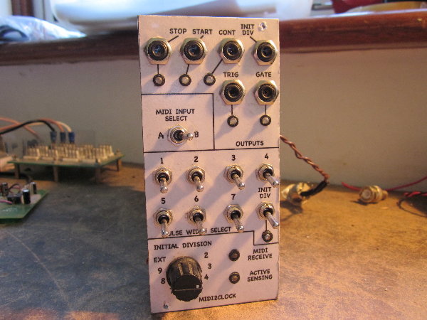
The MIDI2CLOCK (M2C) takes a MIDI input, and outputs 24PPQN CLOCKS, START, CONTINUE and STOP pulses. These can be +5V or +10v by installing links or pairs of resistors. There is also an onboard 2-stage divider network with GATE and TRIGGER outputs, that allows different time signatures, pulse divisions and pulse widths to be set up, using just a rotary switch and 8 SPST changeover toggle switches. No menus or LCDs, or any of that malarkey.
It handles MIDI clocks, not MTC (midi timecode) - MTC is a completely different beastie....
The circuit has been tested operating from 1 BPM to 250 BPM, and will track tempo changes smoothly. The gate length is proportional to the tempo, so slower tempi give longer gate lengths.
There are LED indicators for the various outputs, and a MIDI receive LED that lights when any MIDI signal is present at the circuit's MIDI input.
As well as that, there is a pin-header on the PCB that carries decoded MIDI as CMOS-compatible 8-bit parallel +5V logic, along with other useful internal circuit signals. Other pin-headers on the board allow for expansion to further circuits, eg, more divider stages, or remotely controlling the action of the switches. They could even be used to decode other types of MIDI messages with extra circuits , but that is for the truly adventurous 
There are pin headers too for the transmit section of the main processor (CV to MIDI). It is not used in the basic design, but is there for those who wish to experiment with it. Additional circuitry will need to be added in order to use this function.
There are no programmable ICs used, and no calibration is needed, so it can be simply soldered up and is then ready to go. All components used are in current production as of may 2nd 2011, with only one slightly unusual IC, which is still being manufactured, and is stocked by Digikey, Debco.com, Jameco, Farnell and others.
cheers,
Dave
(edited to include details of PCB run thread)
| Description: |
| 12HP euro format. Yes there *is* a reason why all the jacks are at the top...... |
|
| Filesize: |
454.06 KB |
| Viewed: |
531 Time(s) |
| This image has been reduced to fit the page. Click on it to enlarge. |
|
_________________
"Everything in moderation, including moderation"
Last edited by Dave Kendall on Tue Jun 07, 2011 3:37 am; edited 1 time in total |
|
|
Back to top
|
|
 |
Dave Kendall
Joined: May 26, 2007
Posts: 421
Location: England
Audio files: 3
|
| Posted: Tue May 03, 2011 8:19 am Post subject:
a couple more pics... |
|
|
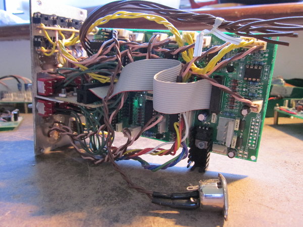
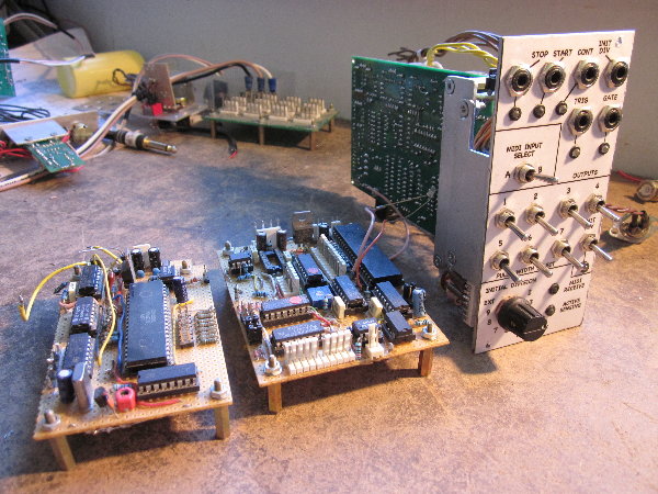
Top one show how cramped the module is in euro....
The bottom one shows the MK1 and MK2 prototypes on perfboard.
| Description: |
|
| Filesize: |
512.44 KB |
| Viewed: |
492 Time(s) |
| This image has been reduced to fit the page. Click on it to enlarge. |
|
| Description: |
|
| Filesize: |
643.9 KB |
| Viewed: |
530 Time(s) |
| This image has been reduced to fit the page. Click on it to enlarge. |
|
_________________
"Everything in moderation, including moderation" |
|
|
Back to top
|
|
|
diablojoy

Joined: Sep 07, 2008
Posts: 809
Location: melbourne australia
Audio files: 11
|
| Posted: Tue May 03, 2011 5:17 pm Post subject:
|
|
|
Well done that is so orsm
will you be releasing the schematic ?
I would be extremely interested in building one of these
A pnp home etch job would be fine but if there were to be a run of boards it would be even better and rightly should attract a lot of interest.
previously i had been looking at doing the ACX synth master clock module but have little PIC programming experience so i think this module would be a far better deal for me
cheers |
|
|
Back to top
|
|
|
fonik

Joined: Jun 07, 2006
Posts: 3950
Location: Germany
Audio files: 23
|
| Posted: Tue May 03, 2011 11:20 pm Post subject:
|
|
|
here are some pics of my built. i decided to spend more front panel estate to keep the module shallow for my new portable suitcase rig.
as you can see, there is a verified/prototyped PCBs already - so if there is enough interest...


(a little bit blurry, sorry)
_________________

cheers,
matthias
____________
Big Boss at fonitronik
Tech Buddy at Random*Source |
|
|
Back to top
|
|
|
tommi

Joined: Dec 05, 2007
Posts: 247
Location: Italy
Audio files: 3
|
| Posted: Wed May 04, 2011 1:37 am Post subject:
|
|
|
Hey Fonik,
Yesterday i saw a picture of your panel on the Matrixsynth blog, and i googled 'Dave Kendall midi clock' with no results. I am glad to see this thread here, i would be very interested in case of a run of pcbs for this project, even if i am not sure what is the exact function of the 8 switches and the rotary one.. i guess two stages of clock division starting from midi's 24ppqn?
Anyway, i was looking to a midi module only for clock and this would be perfect!
cheers
_________________
http://soundcloud.com/mister-vommi
http://tideofsound.net |
|
|
Back to top
|
|
|
fonik
Joined: Jun 07, 2006
Posts: 3950
Location: Germany
Audio files: 23
|
| Posted: Wed May 04, 2011 1:48 am Post subject:
|
|
|
| tommi wrote: | | ...even if i am not sure what is the exact function of the 8 switches and the rotary one.. i guess two stages of clock division starting from midi's 24ppqn?... |
yep. you have one initial divider stage. the output of this initial divider is then routed to the 2nd stage, allowing you to set patterns/divisions/PW etc. think of the 2nd stage divider as of a simple gate sequencer.
maybe dave could chime in? he could explane it much better than me, i bet. i even fear that my labeling of the initial division rotary switch is missleading.
_________________
cheers,
matthias
____________
Big Boss at fonitronik
Tech Buddy at Random*Source |
|
|
Back to top
|
|
|
tommi
Joined: Dec 05, 2007
Posts: 247
Location: Italy
Audio files: 3
|
| Posted: Wed May 04, 2011 2:45 am Post subject:
|
|
|
A gate sequencer, great! I see some difference between the layouts, like an external cv i guess for selecting the initial division of midi clock.. mm! very interesting!
And i see a switch for selecting midi in a or b (not easy to think a practical use for that for me.. maybe i didn't understood his function.. is it just a switch to select from two midi clock sources?).
_________________
http://soundcloud.com/mister-vommi
http://tideofsound.net |
|
|
Back to top
|
|
|
Dave Kendall
Joined: May 26, 2007
Posts: 421
Location: England
Audio files: 3
|
| Posted: Wed May 04, 2011 5:47 am Post subject:
|
|
|
Hi all.
Bit of a long post, but I'll try to explain how the M2C works. It may seem complicated, but when you actually use it, it's dead simple.
Diablojoy - I guess if a PCB run happens, the schematics will be released at the end of the first run, along with a BOM and build/user notes. I'm working on the latter at the moment, though it will take a while due to work pressure.
Tommi - Yes, the two stages divide down from the initial 24PPQN that MIDI clocks arrive in. The initial division divides this down into a more usable number. Let's say it's set to divide by 3. That then gives you 8 PPQN, or 32 beats in a 4-beat bar. With the INIT DIV toggle on, that is what would come out of the GATE and TRIGGER jacks. (The trigger is just a narrow pulse, the gate is variable length)
The second divider stage sets the division *and* pulse width from the GATE out jack, and is controlled by the toggles. It is indeed a gate sequencer, although I originally thought of it as an 8-input OR gate.
For setting pulse widths and divisions, lets set the INITIAL DIVISION to 3.
With Toggles 1,3,5 and 7 ON, you would get 16 beats to the bar from the GATE and TRIGGER out jacks. With 1 and 5 ON, you get 8 beats and so on.
With only toggle 1 ON, you get 4 beats to the bar. If toggle 2 is also ON, the pulse length doubles. With the first 7 toggles ON, you get 4 beats to the bar, but with a pulse length that is *nearly* the whole length of a beat. This is a function of the circuit design, but I think it is a good thing, as, if you trigger an envelope from the GATE out, the gate goes low quickly at the end of the beat, and the envelope is re-triggered at the start of the next beat.
With the INITIAL DIVISION set to divide by 6, you get the same behaviour as above, but the maximum number of beats is now 16, and at the slowest setting (only toggle 1 ON) you get just 2 beats to the bar in 4/4.
If the INITIAL DIVISION is set to divide by 4 or 8, you get a 3/4 meter.
You can have a lot of fun by setting random patterns of the toggles - you get odd rhythms with pulses of different lengths. These can be switched ON and OFF while the thing is running, and it won't affect the sync. Switching the initial division while the sequencer is running gives much more unpredictable results. The other odd numbered divisions in the initial divider (divide by 5, 7 etc.) are there just for fun - a simple build could just have divide by 3 or 4.
I did once test a gate-controlled 2nd divider stage on perfboard, where incoming gates switched the stage 2 dividers ON or OFF. This worked in conjunction with the existing toggles, so that any toggle, when OFF, could be controlled with external gates, and the toggle could overide that, making that stage always ON. I think putting the 8 outputs of Ken Stone's CGS13 gated comparator into this add-on board could be fun.....
The M2C could also be fun with a KLEE, with another set of initial and secondary divisions........
The EXT position on the rotary was a position left for expansion, where the INITIAL DIVISION could also be gate selected. I have some ideas on how to achieve this, it wouldn't be too hard. A possible expansion board could combine a 2nd gate controlled secondary stage, possibly a gate controlled initial stage, and DIN SYNC, which should be easy enough to implement.
Finally, Tommi, you're right again - the MIDI input select switches between two physical MIDI inputs. I always try and run MIDI clocks, and definitely MTC, on its own down a separate MIDI cable from NOTE and other information. MIDI protocol will allow MIDI clocks to be sent in the middle of *any* midi messages, including SYS-EX, so in practice, they can end up delaying other information like note-ons, particularly at faster tempi. There are lots of the little buggers flying around, and MIDI still runs at the same baud rate, so there is less room for notes etc. to be transmitted. I totally recommend using a separate cable for MIDI clocks. These days, multi output MIDI interfaces for computers are cheap enough, so dedicating one from the 8 for clocks, helps a lot to tighten things up. Hence, the select switch - I can either feed the M2C from the dedicated clock line, or another line if needed.
A while back, I had some preliminary ideas about how to implement MIDI PGM changes. It may even be possible to use these to set different patterns in the secondary divider stage, but that would be quite difficult, due to the more complex nature of MIDI PGM change messages. NOTE ON and OFFS are *very* complex by comparison, and I would guess that a whole bunch of logic would be needed for them..... still it's possible - all the raw MIDI data and useful signals, like a SYSTEM REAL TIME flag are on the headers....
Hope this has helped a bit to explain. It *is* easy to use when you have it in your hand, and you can just switch away until you have something you like.
I'll try to get a quick audio demo or two up, to show what it can do.
cheers,
Dave
_________________
"Everything in moderation, including moderation" |
|
|
Back to top
|
|
|
tommi
Joined: Dec 05, 2007
Posts: 247
Location: Italy
Audio files: 3
|
| Posted: Wed May 04, 2011 8:22 am Post subject:
|
|
|
Hello Dave,
Thanks for taking your time for explaining your project in the details.
This project will be great and of course i 'll buy a pcb when/if available.
The toggle control thing is an original feature. The start, stop and continue pulses outputs aren't implemented in any m2cv commercial module as i know, but they are exactly what i was looking for. The Doepfer A-190, wich is the module i am using for synchronising my computer with my modular, is outputting a steady hi when stopped and steady low when running, so i had to use a cgs slope detector to translate these in single pulses to reset my seqencers. With your module i 'd have all these features (and more) all in one.
P.S.: It seems that it's the moment for midi2clock modules! There's this other diy project on the muffwiggler forum (it's based on an arduino board though): http://www.muffwiggler.com/forum/topic-33010.html
_________________
http://soundcloud.com/mister-vommi
http://tideofsound.net |
|
|
Back to top
|
|
|
Dave Kendall
Joined: May 26, 2007
Posts: 421
Location: England
Audio files: 3
|
| Posted: Wed May 04, 2011 8:33 am Post subject:
|
|
|
Hi Tommi.
Glad you like it.
Tombola's design over at Muff's is very cool. Getting swing features in there is a first I think, and it deserves to do very well. I hope it does.
The M2C is a bit of a different beastie, with a different approach. It's really more of a core board for MIDI to modular stuff.
I'm hoping if there's a PCB run, people will come up with ideas and designs for expander circuits, as they can be added without affecting the basic functions.
There is an onboard LM7805 +5V regulator with room for a heatsink, and Doepfer and MOTM format power headers. There is also a power out connector with -15V, +15V +5V and GND on a 4-pin 0.100 header. It should also work fine on ±12V with no component changes.
cheers,
Dave
(edited for typos)
_________________
"Everything in moderation, including moderation" |
|
|
Back to top
|
|
|
diablojoy
Joined: Sep 07, 2008
Posts: 809
Location: melbourne australia
Audio files: 11
|
| Posted: Wed May 04, 2011 4:01 pm Post subject:
|
|
|
| Quote: | | I'm hoping if there's a PCB run, people will come up with ideas and designs for expander circuits, as they can be added without affecting the basic functions. |
| Quote: | | I did once test a gate-controlled 2nd divider stage on perfboard, where incoming gates switched the stage 2 dividers ON or OFF. This worked in conjunction with the existing toggles, so that any toggle, when OFF, could be controlled with external gates, and the toggle could overide that, making that stage always ON. I think putting the 8 outputs of Ken Stone's CGS13 gated comparator into this add-on board could be fun..... |
very nice and the first mod that occurred to me that would be really good
to implement. 
here's hoping for a board run then, definitely in for that if it happens. |
|
|
Back to top
|
|
|
Cynosure
Site Admin

Joined: Dec 11, 2010
Posts: 1025
Location: Toronto, Ontario - Canada
Audio files: 82
|
| Posted: Wed May 04, 2011 6:25 pm Post subject:
|
|
|
| Great stuff! Is it easier to make if all I need is a basic pulse for using with cmos circuits? I'm going to have to build something to eventually that does that. Is it still as complex if that's all I need? What would I be looking at for cost for the components? |
|
|
Back to top
|
|
|
Dave Kendall
Joined: May 26, 2007
Posts: 421
Location: England
Audio files: 3
|
| Posted: Thu May 05, 2011 1:55 am Post subject:
|
|
|
| Quote: | | Is it easier to make if all I need is a basic pulse for using with cmos circuits? |
Yes. If you leave out the divider stages, the output buffers and the toggles and rotary switch, the wiring is drastically reduced. It cuts it down to the main processor section, which would be 7 ICs plus a voltage regulator, and a few caps, resistors and 1N4148 or 1N914 diodes. There are pads for a pin header that carries the 24PPQN clocks, as well as other midi messages. Some unused input pins on one CMOS IC would need to be tied to ground, as per good practice.
I reckon the components will come to around $15 - $20 US without the divider stages. A full build would add 8 SPST toggles, a rotary switch, 6 jacks or bananas, 3 x TL072s and a pair of common CMOS ICs. Not all the headers are vital for the circuit to work, and they could be added later if they are needed. Many or all of the LED indicators could be omitted, although the MIDI Receive LED would be well worth installing. There are a total of 8 indicators, each with a 2N3904 or equivalent transistor, a resistor and a LED. Only 3 resistors really ought to be metal film ones, for stability - they don't need to be very close tolerance. It would probably be OK with carbon 5% ones, but I haven't tried that.
You could still have access to the divider stages without the toggles and rotary, if all the ICs are installed. That way you could remotely control the divider stages using other cmos circuits.
In terms of how much the PC board would cost, that's up to Matthias. It will also probably depend on how many people are interested in a PCB. We'd need a few people in there to make it viable.
cheers,
Dave
_________________
"Everything in moderation, including moderation" |
|
|
Back to top
|
|
|
brother303

Joined: Nov 02, 2010
Posts: 139
Location: ruhr-area/germany
|
| Posted: Thu May 05, 2011 11:23 am Post subject:
|
|
|
Hi,
nice one! I´m in for a pcb if it comes to a run.
_________________
Best regards
Greg |
|
|
Back to top
|
|
|
Cynosure
Site Admin
Joined: Dec 11, 2010
Posts: 1025
Location: Toronto, Ontario - Canada
Audio files: 82
|
| Posted: Thu May 05, 2011 4:23 pm Post subject:
|
|
|
I'm in for a PCB.
Would I need a schematic or instructions to go with it, or will everything be apparent by the labels on the PCB? I'm new to this, and I haven't worked with a printed bored yet - just my own creations on blank circuit board. That's why I'm interested in the CMOS part - because I'm still working with very basic circuits, but I think it would be great if I could sync them up to my computer and other synths. |
|
|
Back to top
|
|
|
Danno Gee Ray
Joined: Sep 25, 2005
Posts: 1351
Location: Telford, PA USA
|
| Posted: Thu May 05, 2011 6:20 pm Post subject:
|
|
|
| I'd be in for one. |
|
|
Back to top
|
|
|
Dego

Joined: Apr 22, 2008
Posts: 139
Location: Sweden
|
| Posted: Fri May 06, 2011 2:35 am Post subject:
|
|
|
I would mod and add din-sync out
I would like a pcb as well |
|
|
Back to top
|
|
|
Dave Kendall
Joined: May 26, 2007
Posts: 421
Location: England
Audio files: 3
|
| Posted: Fri May 06, 2011 9:31 am Post subject:
|
|
|
Hi guys.
Cynosure - there are labels on the board for each component. When the boards go out, the schematic, board layout picture and BOM (bill of materials) listing all parts and possible substitutes will be published here on electro-music for reference. There will also be a build guide, showing any optional parts that can be left out. This will also have a basic connections guide with diagrams.
Dego - DIN SYNC should be very easy indeed. All that is needed is to provide suitable output stages hooked up to one of the pinheaders, and then wired up to a DIN socket. I haven't found an example DIN SYNC buffer or output stage yet, but am looking.... it will be posted once I find something that fits.....
cheers,
Dave
_________________
"Everything in moderation, including moderation" |
|
|
Back to top
|
|
|
diablojoy
Joined: Sep 07, 2008
Posts: 809
Location: melbourne australia
Audio files: 11
|
| Posted: Wed May 11, 2011 4:48 pm Post subject:
|
|
|
strange that this hasn't been peaked a whole lot more people's interest 
I would have thought this to be the project of the year |
|
|
Back to top
|
|
|
fonik
Joined: Jun 07, 2006
Posts: 3950
Location: Germany
Audio files: 23
|
| Posted: Thu May 12, 2011 1:38 am Post subject:
|
|
|
me too...
it realy has been fun to built, and it worked from the start without any isses - and all the blinkin' lights. in fact i never use my klee without it anymore...
_________________
cheers,
matthias
____________
Big Boss at fonitronik
Tech Buddy at Random*Source |
|
|
Back to top
|
|
|
tommi
Joined: Dec 05, 2007
Posts: 247
Location: Italy
Audio files: 3
|
|
|
Back to top
|
|
|
rosch

Joined: Oct 03, 2009
Posts: 165
Location: germany
|
| Posted: Thu May 12, 2011 4:51 am Post subject:
|
|
|
| i'd be in for one, too. |
|
|
Back to top
|
|
|
jksuperstar

Joined: Aug 20, 2004
Posts: 2503
Location: Denver
Audio files: 1
G2 patch files: 18
|
| Posted: Thu May 12, 2011 7:40 am Post subject:
|
|
|
No schematic yet...but is there the possibility of adding a LAG control, so you can turn a know, and delay the CV pulse from the MIDI clock, maybe even move it earlier?
That'd be nice to sync a modular to a MIDI based system, and get notes to align tightly. Or better: make it CV controllable as well, so you can add groove to the beat by adding a gated S&H LFO to the input? |
|
|
Back to top
|
|
|
Cynosure
Site Admin
Joined: Dec 11, 2010
Posts: 1025
Location: Toronto, Ontario - Canada
Audio files: 82
|
| Posted: Thu May 12, 2011 7:50 am Post subject:
|
|
|
| tommi wrote: | | How i 'd like to see it in action.. |
I agree.
Plus, videos get people's attention and might get them to ask for one.
The parts aren't too expensive, so I'll build the full thing just in case I want to use the other functions in the future.
Just let me know who to pay and give my address to once they are ready to sell.
Thanks! |
|
|
Back to top
|
|
|
Dave Kendall
Joined: May 26, 2007
Posts: 421
Location: England
Audio files: 3
|
| Posted: Thu May 12, 2011 8:12 am Post subject:
|
|
|
Hi guys.
Thanks for the interest . I guess I'll have to make a demo video then.......
Am currently refurbishing the modular, so it'll have to be cobbled together for the demo. Work is frantic at the moment , so it might be a few days before it happens.
As far as Lag and CV control go, I haven't thought about that so far.
You've got access to the raw clocks via pin-headers on the board, so delaying them is easy. Moving them *forward* in time is also possible, by delaying the first beat to *just before* it would happen at the second beat.
I'm hoping the video will make things a bit clearer.....
cheers,
Dave
_________________
"Everything in moderation, including moderation" |
|
|
Back to top
|
|
|
|

 Forum index » DIY Hardware and Software


