| Author |
Message |
jumunius
Joined: Apr 19, 2010
Posts: 346
Location: San Francisco, CA
Audio files: 13
|
 Posted: Wed Jun 01, 2011 5:44 pm Post subject:
292c LPG build question -- switching vactrols Posted: Wed Jun 01, 2011 5:44 pm Post subject:
292c LPG build question -- switching vactrols |
  |
|
I'm finally finishing up my 292c Lo Pass Gate, but in testing I've run into a snag. I had added a switch (4PDT) to switch between VTL5C3s and VTL5C4s. My build mostly works, but in LPF mode with resonance set to max and Offset sweeping up from 0, I experience some noise/static sound towards the top of the Offset setting. What appears to happen is when Offset hits 6 or so, the sound cuts out and comes back as noise.
It has been suggested to me that this might be ring modulation between the self-oscillations and some interference, and my switching scheme (which involves a lot of wiring between the vactrols and the board) might be the cause. In moving the deep switch around (as in physically moving the wires) I have made this problem go away, and other times I can play the self-oscillation like a theremin.
So I'm wondering if anyone else made a switch for their vactrols like this, and if so how did you get it to work. I thought I saw someone in the 30+ page 292c thread mention a desire to do this. Did anyone succeed? Suggestions?
I'm seriously considering changing my wiring approach, but I've killed some pads already desoldering this board and I am a bit afraid of doing too much desoldering and resoldering, given that these boards are hard to come by.
For what it's worth, this may or may not be a good idea. Already I can tell the 2 pairs of vactrols seem to respond to offset range very differently, and in the end it means I'll probably have to optimize the trimpot and other build settings for one pair of vactrols (the 3's) at the expense of good range settings for the 4's. |
|
|
Back to top
|
|
 |
The Peasant

Joined: Nov 13, 2009
Posts: 114
Location: Sunny Alberta
Audio files: 1
|
| Posted: Wed Jun 01, 2011 6:21 pm Post subject:
|
|
|
I did this very thing with my 292c build using a 3PDT switch, it seems to work fine. Yes the response is quite different between the two vactrols, and the trimmer setting ends up being a compromise between the two, but I found that the offset control has sufficient range to work fine with both. At extreme settings the sound does drop out, but this is outside of the usable range anyways. The number of connections that you are switching may make a difference, you only really need to switch 3 of them.
Details of the changes that I made can be found about 1/2 way down the page on this Muff Wiggler thread.
http://www.muffwiggler.com/forum/topic-8540-100.html
Take care,
Doug
_________________
The Electronic Peasant
www.electronicpeasant.com |
|
|
Back to top
|
|
|
jumunius
Joined: Apr 19, 2010
Posts: 346
Location: San Francisco, CA
Audio files: 13
|
| Posted: Wed Jun 01, 2011 8:49 pm Post subject:
|
|
|
| The Peasant wrote: | I did this very thing with my 292c build using a 3PDT switch, it seems to work fine. Yes the response is quite different between the two vactrols, and the trimmer setting ends up being a compromise between the two, but I found that the offset control has sufficient range to work fine with both. At extreme settings the sound does drop out, but this is outside of the usable range anyways. The number of connections that you are switching may make a difference, you only really need to switch 3 of them.
|
Yeah, it's been suggested that the action off pin7 of the op-amp could be causing me problems, so I think your scheme resolves that.
How did you mount your vactrols and switch? Any pics or suggestions? Initially I used a daughterboard, so 4 wires running from main board to switch, 8 wires from switch to db, 4 wires running from db to main board. Now I'm thinking of losing the daughterboard to reduce wiring and maybe hot gluing the 3's and 4s to the pcb, piggybacked.
Well, I'll keep my fingers crossed that your mods make a difference in 2 builds in a row. Thanks again! |
|
|
Back to top
|
|
|
negativspace

Joined: Dec 25, 2010
Posts: 17
Location: Manhattan, Kansas
|
| Posted: Thu Jun 02, 2011 1:45 am Post subject:
|
|
|
I did the 3PDT switch on my build as well and I can report no quirky behavior. It's definitely worth doing. I mounted my vactrols on the board, piggybacked. Soldering the unswitched leads on the top part to the bottom part's leads has proven sufficient to keep the 2nd pair mounted, no need for glue.  |
|
|
Back to top
|
|
|
jumunius
Joined: Apr 19, 2010
Posts: 346
Location: San Francisco, CA
Audio files: 13
|
| Posted: Thu Jun 02, 2011 4:54 am Post subject:
|
|
|
| negativspace wrote: | | I did the 3PDT switch on my build as well and I can report no quirky behavior. It's definitely worth doing. I mounted my vactrols on the board, piggybacked. Soldering the unswitched leads on the top part to the bottom part's leads has proven sufficient to keep the 2nd pair mounted, no need for glue. |
Hmm.... How many legs from the first set of vactrols did you mount to the board? The way I read it from Doug's schematic, unless I'm adding holes and traces, vactrol V1 (topmost according to pcb's orientation) would have 2 legs at opposite ends of the vactrol that are mounted, which might be secure enough. But the legs of V2 are only soldered to the board at one end of it, which seems less stable.
Anyways, good to know that you also find it worthwhile. I was starting to wonder if this was a lot of work for limited results. |
|
|
Back to top
|
|
|
The Peasant
Joined: Nov 13, 2009
Posts: 114
Location: Sunny Alberta
Audio files: 1
|
| Posted: Thu Jun 02, 2011 8:16 am Post subject:
|
|
|
| jumunius wrote: | | How did you mount your vactrols and switch? Any pics or suggestions? Initially I used a daughterboard, so 4 wires running from main board to switch, 8 wires from switch to db, 4 wires running from db to main board. Now I'm thinking of losing the daughterboard to reduce wiring and maybe hot gluing the 3's and 4s to the pcb, piggybacked. |
I mounted the extra vactrols on the pcb squeezed in next to the first two. The switch is mounted on the panel with the other controls and shielded wires are used to connect it to the pcb. I can post some pictures later tonight if you like.
Take care,
Doug
_________________
The Electronic Peasant
www.electronicpeasant.com |
|
|
Back to top
|
|
|
jumunius
Joined: Apr 19, 2010
Posts: 346
Location: San Francisco, CA
Audio files: 13
|
| Posted: Thu Jun 02, 2011 9:47 am Post subject:
|
|
|
[quote="The Peasant"] | jumunius wrote: | I mounted the extra vactrols on the pcb squeezed in next to the first two. The switch is mounted on the panel with the other controls and shielded wires are used to connect it to the pcb. I can post some pictures later tonight if you like.
|
If it's not too much trouble, pictures would be nice. I may be a little limited with my options, depending on how far I've cut down my leads at this point, but I would love to see how others have accomplished this.
Thanks! |
|
|
Back to top
|
|
|
The Peasant
Joined: Nov 13, 2009
Posts: 114
Location: Sunny Alberta
Audio files: 1
|
| Posted: Sun Jun 05, 2011 10:43 am Post subject:
|
|
|
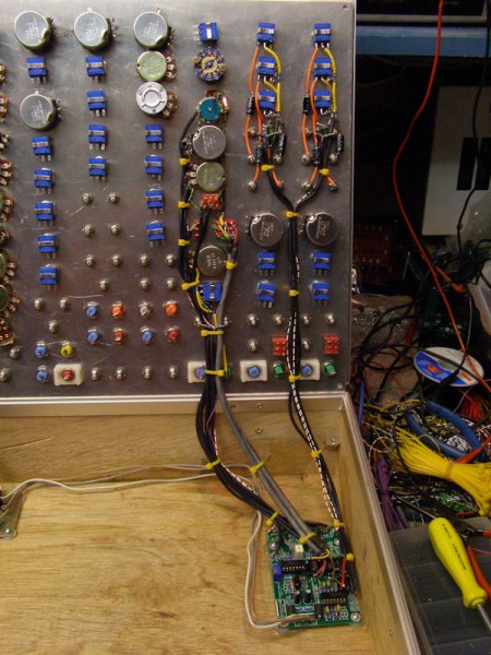
Sorry for the delay, here is a picture of the circuit board with the extra two vactrols mounted on the right hand side, as indicated by the arrows. Also, there is a picture of the board wired up to the front panel. The mixer circuits on the pcb were wired as two independant mixer modules.
Take care,
Doug
| Description: |
|
| Filesize: |
97.1 KB |
| Viewed: |
219 Time(s) |
| This image has been reduced to fit the page. Click on it to enlarge. |

|
| Description: |
|
| Filesize: |
148.94 KB |
| Viewed: |
223 Time(s) |
| This image has been reduced to fit the page. Click on it to enlarge. |
|
_________________
The Electronic Peasant
www.electronicpeasant.com |
|
|
Back to top
|
|
|
jumunius
Joined: Apr 19, 2010
Posts: 346
Location: San Francisco, CA
Audio files: 13
|
| Posted: Mon Jun 06, 2011 12:26 am Post subject:
|
|
|
Thanks Doug. Well the good news is your pics came in about the same time I was starting to rewire things. The bad news is that in the process of rewiring, one of my VTL5C4s lost a leg. (It had been mounted and unmounted from the pcb, then mounted and unmounted from a daughterboard, and in moving everything back to the pcb it gave up the ghost.) Not having a spare I'm finishing the wiring with just the VTLSC3's mounted to the switch for now and deal with the 4's next time I order parts.
The other bad news is that now that I board-mounted the VTL5C3s, redoing the switch to be a 3PDT, etc, I test it out again and essentially nothing has changed, except maybe even for the worse. The thing sounds good for most of the offset range when resonance is at a lower setting, but once resonance crosses a (lowish) threshhold the output levels skyrocket, and with resonance above this point, the upper regions of offsetl turn the signal into something that sounds like a radio between stations.
It's good to see how you crammed the extra ones in there. I have some headers along the edge of the board which may or may not get in the way, but I like to have some ideas of how to proceed.
Also in the process of doing this I learned that I fundamentally misunderstood the layout of vactrols. Since my board rev and my vactrols only had a + symbol, I somehow got the idea that the "pinout" of a vactrol was 90 degrees rotated from what it actually is (the LED and resistor running length-wise, not width-wise). So my original switch concept was not only inelegant, but flawed.  Sadly now that my wiring is corrected, and far shorter, nothing has changed. Sadly now that my wiring is corrected, and far shorter, nothing has changed. 
Well, onto more troubleshooting. |
|
|
Back to top
|
|
|
jumunius
Joined: Apr 19, 2010
Posts: 346
Location: San Francisco, CA
Audio files: 13
|
| Posted: Wed Jul 27, 2011 1:28 am Post subject:
|
|
|
Ok, I'm having more luck with this build, and was able to resuscitate my amputee VTLSC4 and fix up this switch. I ended up mounting my 2nd set of vactrols *beneath* the board, which seems to work ok too. Since they'd been remounted a few times the legs were short and obviously not very sturdy (as one had broke) so this seemed safest physically.
Now for a question and a comment. Firstly, do you notice a pronounced difference in the resonance character between VTLSC3 and 4? My 3 has a very nice, cutting resonance. My 4 is pleasant, but seems tame by comparison, and doesn't self-oscillate. Messing around with the value of R18 helped but the resonance generally sounded more clipped, less precise.
Secondly, it struck me that since I'm using a 4PDT to switch only 3 legs on the vactrols, I can use the 4th pole to switch a resistor either parallel or in series with R19 (the deep switch resistor). Adding 100k of resistance total seems to balance the offset levels such that the vactrols' cutoff is complimentary when you switch back and forth. Now if I could only get the resonance to match. |
|
|
Back to top
|
|
|
emdot_ambient
Joined: Nov 22, 2009
Posts: 667
Location: Frederick, MD
|
| Posted: Wed Jul 27, 2011 9:18 am Post subject:
|
|
|
| jumunius wrote: | | ...Adding 100k of resistance total seems to balance the offset levels such that the vactrols' cutoff is complimentary when you switch back and forth. Now if I could only get the resonance to match. |
Good to know. I've still got 2 of these to build along with fonik's gate controlled switch expansions and was thinking of doing both with selectable vactrols.
_________________
Looking for a certain ratio since 1978 |
|
|
Back to top
|
|
|
jumunius
Joined: Apr 19, 2010
Posts: 346
Location: San Francisco, CA
Audio files: 13
|
| Posted: Wed Jul 27, 2011 9:26 am Post subject:
|
|
|
[quote="emdot_ambient"] | jumunius wrote: |
Good to know. I've still got 2 of these to build along with fonik's gate controlled switch expansions and was thinking of doing both with selectable vactrols. |
I was just thinking about that myself but don't have the fonik switches. If I had it to do over again I'd do a few things differently on the build, and that would be one.
BTW You might plan to test resistance values there... I've read there's a bit of variance between vactrols. |
|
|
Back to top
|
|
|
The Peasant
Joined: Nov 13, 2009
Posts: 114
Location: Sunny Alberta
Audio files: 1
|
| Posted: Wed Jul 27, 2011 12:46 pm Post subject:
|
|
|
On my build there is a definitely a difference between the response of the two different vactrols, but they both resonate similarly, just at different settings. Their character is a little different, but not by very much.
Take care,
Doug
_________________
The Electronic Peasant
www.electronicpeasant.com |
|
|
Back to top
|
|
|
|

 Forum index » DIY Hardware and Software
