| Author |
Message |
nop.debouwer
Joined: Dec 06, 2012
Posts: 5
Location: the Netherlands
|
 Posted: Thu Dec 06, 2012 2:50 am Post subject:
Soundlab minisynth plus VCO2 problem Posted: Thu Dec 06, 2012 2:50 am Post subject:
Soundlab minisynth plus VCO2 problem |
  |
|
Hi all,
I'm trying to build the soundlab minisynth plus. Actually it works almost perfectly except for VCO2. It doesn't track 1V/Octave. If I calibrate over a 2 volt range (0-2V) It does get calibrated. However, every voltage between 0- and 2V is way off! except for 0- and 2V? I went over the wiring and parts values and can't find anything wrong. Does anyone have an idea what could cause this strange behavior?. I saw a post with similar problems but apparently he/she misplaced two parts wich is not the case in my soundlab.
any help would be greatly appreciated. |
|
|
Back to top
|
|
 |
elmegil

Joined: Mar 20, 2012
Posts: 2177
Location: Chicago
Audio files: 16
|
| Posted: Thu Dec 06, 2012 6:24 am Post subject:
|
|
|
Funny you should ask, I had something similar with an original SLMS recently....
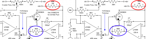
O1 would track over 2 octaves and then fall apart, and O2 wouldn't even do that. Turned out that R56 & R64, and R59 & R65 had wrong value resistors in them. They're supposed to be 1M and 10k respectively in each pair, but there were two 10ks for R56 & R64, and two 1Ms for R59 & R65. Lucky for this conversation, the resistor numbers and values are the same for both schematics (SLMS original and SLMS+).
So triple check the resistor values there, and probably throughout the rest of the expo converter section (everything around IC5A & B and IC6A & B), and I bet you will find your problem. |
|
|
Back to top
|
|
|
nop.debouwer
Joined: Dec 06, 2012
Posts: 5
Location: the Netherlands
|
| Posted: Thu Dec 06, 2012 6:45 am Post subject:
|
|
|
Thanx for your reply,
I think I was reffering to your post  . Do you mean that R56&64 should be 1M and the other two R59&65 10k? . Do you mean that R56&64 should be 1M and the other two R59&65 10k? |
|
|
Back to top
|
|
|
elmegil
Joined: Mar 20, 2012
Posts: 2177
Location: Chicago
Audio files: 16
|
|
|
Back to top
|
|
|
nop.debouwer
Joined: Dec 06, 2012
Posts: 5
Location: the Netherlands
|
| Posted: Thu Dec 06, 2012 8:56 am Post subject:
|
|
|
 You are confusing me a bit. As I said in the first message: I did not switch/mix-up these resistors. Or do you mean that there is an error in the layouts/schematics from Ray? You are confusing me a bit. As I said in the first message: I did not switch/mix-up these resistors. Or do you mean that there is an error in the layouts/schematics from Ray? 
I will take a closer look at the expo-con's and see if I made a mistake there.
The thing that gets me puzzled is the fact that at 0V (I know, can't be wrong at 0V) and 2V gives the correct frequencies ([f(V=0)]x4) but anything >0V & <2V is off.
nevertheless, thanks again. |
|
|
Back to top
|
|
|
elmegil
Joined: Mar 20, 2012
Posts: 2177
Location: Chicago
Audio files: 16
|
| Posted: Thu Dec 06, 2012 9:37 am Post subject:
|
|
|
If you've checked and rechecked then that's fine. Ray's schematic is right.
Many times I have been baffled by troubleshooting something, been totally convinced it was wired correctly, and then turned out I did have a problem somewhere that I only saw the third or fourth time I looked at it.
Perhaps there's not a component value problem, but a solder bridge or something in that area?
What I saw with my own mistake here was that I could calibrate O1 so that it was right on at 0 & 2V, but 1V was a bit sharp (but not so much that it worried me a lot), and everything after 2V was flat. O2 originally was so bad I couldn't calibrate it without changing the 2K feedback resistor to 2.2K, and then it behaved more or less the same; calibrate at 0 & 2V, but then 1V was off (more than O1 at 1V) and after 2V was WAY off. |
|
|
Back to top
|
|
|
nop.debouwer
Joined: Dec 06, 2012
Posts: 5
Location: the Netherlands
|
| Posted: Thu Dec 06, 2012 9:59 am Post subject:
|
|
|
I will take a look at it tonight. I've learned about solderbridges and cold solderjoints the hardway (too)  Now I tripple check every trace and joint with a BIG magnifying glass and multimeter Now I tripple check every trace and joint with a BIG magnifying glass and multimeter  . .
Hope I will find the error/faulty part toninght.
I will keep you posted |
|
|
Back to top
|
|
|
nop.debouwer
Joined: Dec 06, 2012
Posts: 5
Location: the Netherlands
|
| Posted: Sun Dec 09, 2012 1:14 am Post subject:
|
|
|
| Wow, it did turned out to be a wrong resistor value . Problem was R61. I had a 1k instead of 2k. Red and brown color codings are hard to distinguish in poor artificial light. |
|
|
Back to top
|
|
|
elmegil
Joined: Mar 20, 2012
Posts: 2177
Location: Chicago
Audio files: 16
|
| Posted: Sun Dec 09, 2012 2:42 am Post subject:
|
|
|
| Glad you have it sorted |
|
|
Back to top
|
|
|
Uncle Krunkus
Moderator

Joined: Jul 11, 2005
Posts: 4761
Location: Sydney, Australia
Audio files: 52
G2 patch files: 1
|
| Posted: Sun Dec 09, 2012 3:36 am Post subject:
|
|
|
I was about to say that I agreed with you elmegil, in that I thought it unlikely that the MPF102 had gone, but that it was more likely the resistors you were pointing out.
Resistor values are taken for granted more often than they should.
Sure,.. if you're bashin some idea around on a breadboard, play with values as much as you like. Even find the odd strange value you might not have tried,.....but,....
When you're building a tested PCB design for a specific end,....... check everything!!! 
Why not? 
Are you planning on re-building this again real soon? ( to get a working one?)
It's hard to put into words, but when you've troubleshooted things for a while, you'll see that most faults are value/connector related, and these are both things which you have the power to eliminate from you're troubleshooting before you even start building.
Okay,.. I'll stop my ranting now and return you to your regularly scheduled viewing! 
Just hope it helps someone!
_________________
What makes a space ours, is what we put there, and what we do there. |
|
|
Back to top
|
|
|
|

 Forum index » DIY Hardware and Software » MusicFromOuterSpace.com designs by Ray Wilson