| Author |
Message |
PHOBoS

Joined: Jan 14, 2010
Posts: 5881
Location: Moon Base
Audio files: 709
|
 Posted: Sat Jan 12, 2013 8:27 pm Post subject:
Tim Escobedo's PWM - PHOBoS mod Posted: Sat Jan 12, 2013 8:27 pm Post subject:
Tim Escobedo's PWM - PHOBoS mod
Subject description: no signal indicator/peak indicator/divider |
  |
|
I was browing Draal's blog while I was waiting for some paint to dry and stumbled upon
Tim Escobedo's PWM circuit.

I was thinking of making some circuits to convert music to other usefull control signals and this looked simple enough
to give it a try. So I breadboarded the circuit and started modifying it.
The first thing I did was remove the bridge between pin1 and 8 which sets the gain to 200x. If you want to use a guitar
(what the circuit was originally intended for) or a microphone this amount of gain is useful but I will be using it for
line level signals. I also added an attenuator for some better input level control. The capacitor/resistor feedback loop
between output and pin 1 is something I found in an old electronic magazine (ELEX) and was labeled bass boost, but it
sounds like it actually filters out the high frequencies.
The original circuit only uses 2 of the 6 inverters so I started to think about what I could use the other ones for.
To get a bit of an indication about the input level I added a peak indicator: First the offset voltage of the LM386
get's removed by a capacitor/resistor, then the positive part of the signal is used to charge a capacitor. If this
voltage get's high enough the transistor pulls the input of U2e below the treshold level and it's output goes high.
I selected the values by checking the output of the LM386 with my scope so that the LED turns on just when it starts
to distort. [You could use this circuit as an addition whenever you use an LM386 amp and if you don't want to use an
extra schmitt trigger inverter you could just use the transistor to drive a LED directly. However it will not turn nicely
on and off and you will probably have to change some component values a bit to get a nice indication.]
I still had 3 inverters left but before I used those I added the 4040 divider. This is something Draal also mentioned
and it works great to turn the input signal into related CLK signals. Just for fun I added the RGB LED, but you can leave
it out of course, allthough it does look very nice 
This LED is also where the idea for the 'no signal' output came from. Basically I just wanted to turn it off when there
was no music and for this I needed to make the reset input of the 4040 high.
I made a similar circuit as for the peak indicator but without the transistor so it's output goes low when the
capacitor is charged. However sometimes it worked fine and the indicator LED would turn on when there was no signal,
but other times it would stay off. I took a look at the ouput of U2a and it behaved the same. so I checked the output
of the LM386 and, as I could have allready guessed, it's at 1/2 the supply voltage when there is no input signal. And
because this is between the treshold levels of the 40106 it behaves unpredictable (I think). To solve this I added a
voltage divider so instead of 1/2 the supply voltage the input of U2a is now below it's treshold level and it's output
will be high, this get's inverted by U2b for the 'No Signal' circuit. With the current component values it tuns on after
about 1 second of silence or when the input level is too low. I am thinking of adding a bigger capacitor and replace the
470K resistor with a pot to make this time adjustable.
And finally U2d was added so the output is low without an input signal. Since the 4040 is triggered by a high to low
transistion I used the output from U2c (inverted) but with these signals it doesn't really matter. There's also a line
output with level control to use it as an audio effect processor. (it's original purpose) 
| Description: |
| Tim Escobedo's PWM circuit with mdifications by PHOBoS |
|
| Filesize: |
56.54 KB |
| Viewed: |
1778 Time(s) |
| This image has been reduced to fit the page. Click on it to enlarge. |
|
_________________
"My perf, it's full of holes!"
http://phobos.000space.com/
SoundCloud BandCamp MixCloud Stickney Synthyards Captain Collider Twitch YouTube
Last edited by PHOBoS on Sun Jan 13, 2013 12:48 pm; edited 1 time in total |
|
|
Back to top
|
|
 |
Draal

Joined: May 18, 2010
Posts: 308
Location: Oak Park, IL
Audio files: 5
|
| Posted: Sun Jan 13, 2013 6:31 am Post subject:
|
|
|
Good idea to think about that gain reduction on the 386. I've run keyboards through it and the signal is hot for sure. Useable, but distorted (this may be acceptable for some of us alchemists  ). Perhaps I'll consider a switch or adjustable gain setup when I get some free time. ). Perhaps I'll consider a switch or adjustable gain setup when I get some free time.
It's very cool to be able to add distorted vocals in the mix when plugging away/recording or use your voice to trigger other sequences. All of a sudden, you are adding an organic , unpredictable element to setting up a sequence or adding true randomness.
More fun: Connect the output of the PWM to the 4046 Pitch Tracker for a simple device that will transform anything you input: voice, instrument, contact mic, into warped out sounds. I've tried tapping on various things close to the mic as well as contact mics for lo fi drum sounds too.
It's a fun module or building block in any lunetta for sure. I wanted something to square up my guitar and mic signals so I could incorporate them as triggers or sonic shapers in my machine.
With your mods, it'll be interesting to see what line level elements can be put into the mix. Time to experiment....
_________________
Zontar Prevails! |
|
|
Back to top
|
|
|
PHOBoS
Joined: Jan 14, 2010
Posts: 5881
Location: Moon Base
Audio files: 709
|
| Posted: Sun Jan 13, 2013 11:45 am Post subject:
|
|
|
| Draal wrote: | | Good idea to think about that gain reduction on the 386. I've run keyboards through it and the signal is hot for sure. Useable, but distorted (this may be acceptable for some of us alchemists ). Perhaps I'll consider a switch or adjustable gain setup when I get some free time. |
The amount of gain you need also depends on what you use it for, if you want some CLK signals,. it works nice if
you set the level so it just clips, however the input signal is much more recognizable if you turn the gain up a lot.
So I'm gonna add a switch aswell,. but as far as I know you should add a capacitor between those pins, not just short them
allthough that seems to work too. wait let me check the datasheet 
| Quote: | To make the LM386 a more versatile amplifier, two pins [1 and 8] are provided for gain control.
With pins 1 and 8 open the 1.35 kΩ resistor sets the gain at 20 (26 dB). If a capacitor is put from pin 1 to 8,
bypassing the 1.35 kΩ resistor, the gain will go up to 200 (46 dB). If a resistor is placed in series with the
capacitor, the gain can be set to any value from 20 to 200. |
So I guess I'll put a cap in there.
btw it continues with
| Quote: | | Gain control can also be done by capacitively coupling a resistor (or FET) from pin 1 to ground. |
that might be usefull  (maybe I can add automatic gain control (maybe I can add automatic gain control  ) )
| Quote: | | More fun: Connect the output of the PWM to the 4046 Pitch Tracker for a simple device that will transform anything you input: voice, instrument, contact mic, into warped out sounds. I've tried tapping on various things close to the mic as well as contact mics for lo fi drum sounds too. |
Allthough my VCO isn't exactly the same as the pitch tracker (I think) it does have a track function, and yes
that's a lot of fun,.
I also like it a lot when you connect the outputs of the divider to an R2R -> VCO for input signal related beeps
this is where the "No Signal" output comes in handy, using it to reset the 4040 means (in my case) that the VCO
is silent when there is no input signal, it will probably work very nice with a pickup mic. which reminds me that I
should try my mini springboard, see what that does.
| Quote: | | It's a fun module or building block in any lunetta for sure. I wanted something to square up my guitar and mic signals so I could incorporate them as triggers or sonic shapers in my machine. |
I only did a couple of quick tests but I agree,. it's very usefull and lotsa fun, and as you mentioned: it adds an organic, unpredictable element. 
edit: I added the pot to set the time for the "No Signal" output, which works great, I'll post an updated schematic later
but I might make some more changes first. I'm actually thinking of placing it in a box together with a 4046 VCO
and R2R to use it as a standalone signal to bleeps/sweeps/warbles/noise converter. (or save it up for a bigger box
with multiple circuits).
_________________
"My perf, it's full of holes!"
http://phobos.000space.com/
SoundCloud BandCamp MixCloud Stickney Synthyards Captain Collider Twitch YouTube |
|
|
Back to top
|
|
|
analog_backlash

Joined: Sep 04, 2012
Posts: 393
Location: Aldershot, UK
Audio files: 21
|
| Posted: Thu Jan 17, 2013 7:14 am Post subject:
|
|
|
I'd seen Tim Escobedo's PWM circuit a long time ago and thought about building it as a guitar effect (but never did, of course). Now, it's just another addition to my impossibly long list of things I'd like to try.
Sometimes, my enthusiasm wains and I don't get as much done. I'd like to know how you keep your amazing pace up - are you really just one person, or a collective working towards a common goal? Sorry, getting a bit SF again there...
Gary |
|
|
Back to top
|
|
|
PHOBoS
Joined: Jan 14, 2010
Posts: 5881
Location: Moon Base
Audio files: 709
|
| Posted: Thu Jan 17, 2013 11:41 am Post subject:
|
|
|
| analog_backlash wrote: | | Sometimes, my enthusiasm wains and I don't get as much done. I'd like to know how you keep your amazing pace up - are you really just one person, or a collective working towards a common goal? Sorry, getting a bit SF again there... |
LOL, It's just us 3, that is me, myself and I, and we all want to work on something different (it sometimes does get
a bit crowded in my head). But it's pretty much all I do besides a parttime job and I still waste time reading and looking
at things on the internet too.
But sometimes I do get bored with a project,. which is one of the reasons I always have several things going at once.
And making music with the things I build is a nice break too, allthough that often gives me new ideas 
_________________
"My perf, it's full of holes!"
http://phobos.000space.com/
SoundCloud BandCamp MixCloud Stickney Synthyards Captain Collider Twitch YouTube |
|
|
Back to top
|
|
|
PHOBoS
Joined: Jan 14, 2010
Posts: 5881
Location: Moon Base
Audio files: 709
|
|
|
Back to top
|
|
|
new voodoo
Joined: May 06, 2013
Posts: 94
Location: RVA USA
|
| Posted: Sat Mar 28, 2015 4:34 am Post subject:
q |
|
|
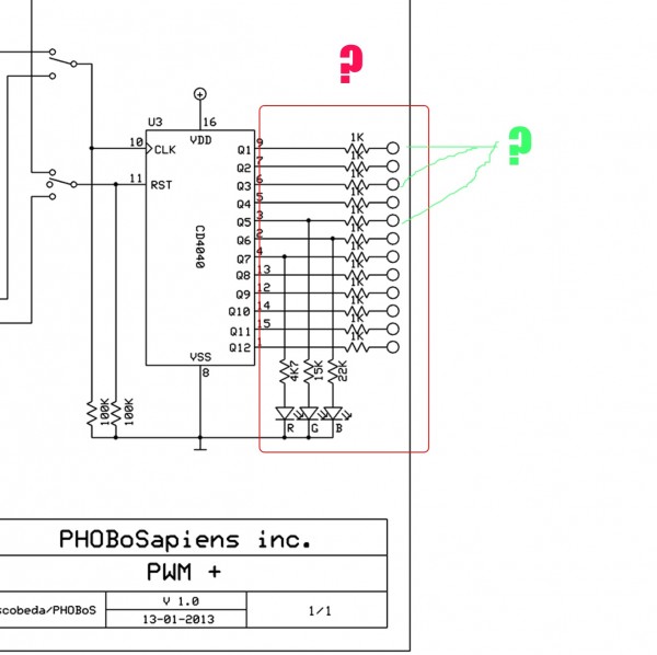
im not sure I get what is going on here (see photo-section marked in green and red)-it looks sorta like a resistor ladder but where id expect to see the output on one side and ground on the other it isnt set up that way.
Are you using it as an arpeggiator to send increasing voltages repeatedly? or to do DAC?(seems unlikely)
Also, the circles (if it was standard ladder) would be digital inputs (as per # of bits and n-bits )..but im thinking thats not the case here-so what are the circles ive marked in green?
Im sorry if these are stupid questions, im just curious and i honestly dont know the answers.
| Description: |
|
| Filesize: |
163.25 KB |
| Viewed: |
659 Time(s) |
| This image has been reduced to fit the page. Click on it to enlarge. |
|
| Description: |
|
| Filesize: |
163.25 KB |
| Viewed: |
612 Time(s) |
| This image has been reduced to fit the page. Click on it to enlarge. |

|
_________________
www.newvoodoodesign.com
-my creations, bends & bendable pieces
-vintage parts & tubes, IC's & audio chips
-oddities & weird
newvoodoo.blogspot.com
-bending DIY/projects
-crap |
|
|
Back to top
|
|
|
PHOBoS
Joined: Jan 14, 2010
Posts: 5881
Location: Moon Base
Audio files: 709
|
| Posted: Sat Mar 28, 2015 6:12 am Post subject:
Re: q |
|
|
The 1K resistors are just current limiting resistors to protect the outputs of the 4040 divider chip in case of a short.
I guess you could connect all the outputs together to create a voltage but that's not what they are intended for.
The circles are the connection-/patch points which in my case are M3 bolts.
I also have LEDs on all the outputs as can be seen in the updated schematic.


_________________
"My perf, it's full of holes!"
http://phobos.000space.com/
SoundCloud BandCamp MixCloud Stickney Synthyards Captain Collider Twitch YouTube |
|
|
Back to top
|
|
|
|

 Forum index » DIY Hardware and Software » Lunettas - circuits inspired by Stanley Lunetta

