prgdeltablues
Joined: Sep 25, 2006
Posts: 222
Location: UK
Audio files: 12
|
 Posted: Sat Jun 08, 2013 6:51 am Post subject:
Visualizer Posted: Sat Jun 08, 2013 6:51 am Post subject:
Visualizer |
  |
|
A couple of people commented on my visualizer module that I posted in the 2013 build post, so I thought I'd start a new topic.
The Visualizer is a crude oscilloscope module, running of +/- 12V, and using a 16x16 LED array for the display. It has X and Y inputs, with scale and offset for both, and has an internal ramp VCO which can be used instead of the X input to scan waveforms.
Here's a link to a video of the Visualizer in X-Y mode,showing some examples of chaos:
https://www.dropbox.com/s/297fgg40a7y8xd4/Visualiser%20Chaos.mov
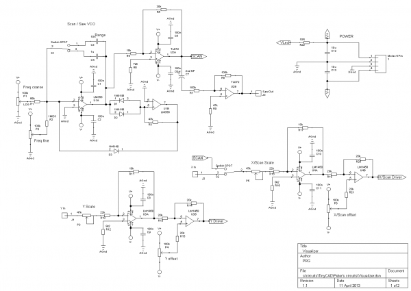
Schematics are below. The circuit is based around two pairs of LM3914 bargraph drivers. These only like positive going signals, and are here set for maximum range of 5V. So incoming signals - which could be a 5V P-P wave, 0-5V LFO, or a rail-to-rail signal, need to be scaled and offset to be 0-5V.
The X signal comes in through P4, which provides scaling adjustment, is roughly halved and inverted by U4A, then reinverted by U4B and a DC offset applied by P6. The Y signal is similarly treated by an identical sub-circuit around P3, U3 and P4.
The X input can also instead via switch S2 take the output from the Scan/VCO. This is Nicolas' simple Hz/V VCO, with both coarse and fine frequency adjustments provided by P1 and P2, and a range switch (which changes the timing capacitor between 10nF and 1uF). The available range is from about 3Hz to about 3kHz.
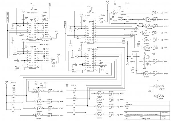
On the second sheet, the X output from U4B is feed into the input of a pair of LM3914s, U5 and U6, set up as per the datasheet to provide a 20-LED dot mode output. 2k resistors on pin 7 set the LED current at about 20mA, and R24/R25 between pins 6/7 and 8 set the upper end of the internal resistor chain to about 5V. The first output on Pin 1 is connected to an LED as an 'undervoltage' warning indicator, Outputs 2-17 go to two 8x8 LED arrays (not shown on the schematic), and output 18 is an 'overvoltage' indicator.
NOTE that the LM3914 does not output a voltage, but provides an on/off current sink. (This means you can't check if it is working by using a DVM - just use an LED.) There is no need for current limiting resistors, as that is done internally (with the resistor on Pin7 setting the LED current).
The outputs from the X-dimension LM3914s are connected to the cathodes of the LED arrays. When an output pin on the LM3914 is selected, it provides a current sink to ground.
The circuitry for Y is essentially the same, but here the outputs of U7 and U8 feed the inputs of a series of schmitt inverters (40106s). There are pull-up 10k resistors on all the inputs. The outputs of the 40106's go though a diode (1N4148) to the anode pins of the LED arrays. This means that when a 'Y' pin is not selected, no current flows into the LM3914, so the input of the 4016 is held high, and thus the output is low. When a Y pin is selected, current can flow, pulling the 40106 input sufficiently low that its output goes high.
The result of all this is that only one LED in the array is lit at a time. This is because there is only one combination of row and column in the array for which the LED anode is high and the cathode low. All other LED have either both high, or both low, or else would have the anode low and the cathode high - a reverse voltage which would destroy the LED. This is prevented by the diodes on the outputs of the 40106's (LED's are quite vulnerable to reverse voltages, but 1N4148s are not.)
The LED arrays I used are 8x8 Kingbright TA15-11SRWA 14.2mm Red LED Display Anode (Rapid UK parts number 57-0696). These are column anode. They have the most bizarre pinouts imaginable, which I shan't attempt to describe. On the schematic, the second output of the first X LM3914 (which drives the first column of the display), is connected to Pin 5 of the bottom left LED array. And so on.
There's a lot of inter-array wiring needed. If you imagine the four arrays being Bottom Left (BL), top left (TL), bottom right (BR) and top right (TR), then the first eight X-outputs go to BL, with interconnects to the equivalent pins on TL, and the second eight X outputs go to BR, with interconnects to TR. Likewise, the first eight Y outputs go to BL (which means all the pins on the BL array are wired to the board), with interconnects to BR, and the second eight Y outputs go to TL, with interconnects to TR. TR thus has no direct wires to the board.
Peter
| Description: |
|
| Filesize: |
26.53 KB |
| Viewed: |
231 Time(s) |
| This image has been reduced to fit the page. Click on it to enlarge. |
|
| Description: |
|
| Filesize: |
38.94 KB |
| Viewed: |
259 Time(s) |
| This image has been reduced to fit the page. Click on it to enlarge. |
|
|
|
elmegil

Joined: Mar 20, 2012
Posts: 2179
Location: Chicago
Audio files: 16
|
| Posted: Sat Jun 08, 2013 12:23 pm Post subject:
|
|
|
"These only like positive going signals, and are here set for maximum range of 5V."
So I understand this, but is there anything here to protect them from over range signals?
Do you normally start with the scale at zero before plugging anything in to protect them?
Thanks.... |
|
prgdeltablues
Joined: Sep 25, 2006
Posts: 222
Location: UK
Audio files: 12
|
| Posted: Mon Jun 10, 2013 1:34 am Post subject:
|
|
|
According to the datasheet, they can handle 35V above ground without any protection. All that happens if you exceed the reference voltage range is that the highest LED would remain lit. That is a slight problem in my set-up, as I'm not using the highest two LED outputs. So if the voltage is too high (say the signal is high, and I've got the offset turned fully the wrong way, then no LEDs light up. Tweaking the offset will bring something into range.
The default set-up I use is, with no inputs, adjust both offsets so that a single LED near the centre is lit ( a minor problem with a 16x16 array is that there is no actual centre LED!). Then put the X-switch to scan mode. That should produce a line of lit LEDs across the middle of the display. Adjust X scale until the whole width is lit, with neither under nor over voltage LEDs lit (this may require tweaking the offset a bit too). Switch back to X mode, put an sine or triangle wave into Y, and a saw from the same VCO into X. You should see a single sinewave period displaying. Adjust Y scale and offset as above until the waveform just fits the display.
With the values in the schematic, a 10V P-P input will have scale at about max.
Peter |
|

 Forum index » DIY Hardware and Software


