PHOBoS

Joined: Jan 14, 2010
Posts: 5908
Location: Moon Base
Audio files: 709
|
 Posted: Mon Sep 16, 2013 10:13 am Post subject:
stupid idea for a patchable pattern generator Posted: Mon Sep 16, 2013 10:13 am Post subject:
stupid idea for a patchable pattern generator
Subject description: could be used as a sequencer |
  |
|
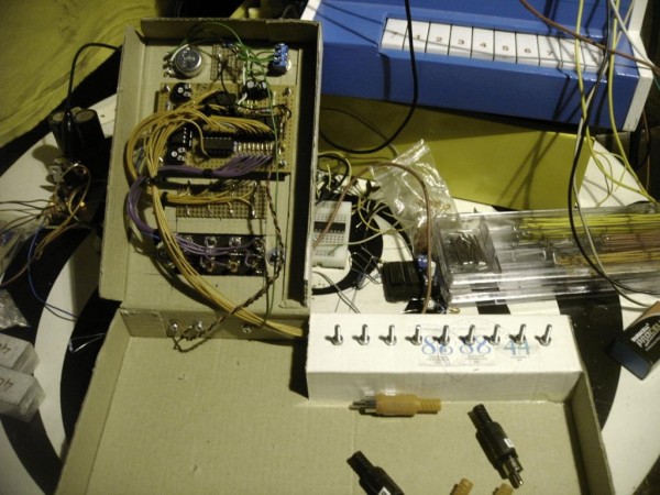
I want to make a patch matrix with cinch (RCA) connectors and while checking my inventory I found a
piece of plastic with 8 busses mounted on it, looks like this:

and I wondered if i could use it somehow as a patchbay for a simple sequenced VCO.
First idea I got was connect 8 outputs of a counter (4017) to the busses and put different resistors in the connectors to control the pitch of an
oscillator. You could make connectors with all kinds of different values and make sequences with that. something like this:
(probably how I got the idea)
But getting it tuned would be very hard, could still be fun though. So the next thing I added was an LM3914 which works a bit like a quantizer.
The LM3914 has a bunch of comparators and with the resistor values I choose there's a ±1V different between the reference levels. So with an
input voltage of 1.5V the first output is on, 2.5V the second, 3.5V the third etc. With pin 9 not connected it's set in dot mode so only one output is on
at a time (there is a small overlap but that doesn't matter for this use). Because they are about 1V apart it's pretty easy to create the right
voltage by using the connectors together with another resistor as a voltage divider. The next thing would be to connect the outputs of the
LM3914 to (trim)pots so you can tune each step.
So if you would make 8 different connectors you could change the pattern like in the video. But of course it's more fun with more connectors so you
can repeat tones and leave others out. But this is where it gets stupid because to make good use of that you would need a lot of them (64 for all
the different combinations). while you could do the same thing with 8 rotary/slide switches and then you don't need the LM3914.
But I decided to draw a schematic anyway and test it. Because the LM3914 has 10 outputs and I only need 8 steps, I used the last one to
control the reset. So by using a connector with a 1K resistor (or shorted) you can set the number of steps. And the initial idea behind the the first
(X) output was to turn a 4046 VCO off (so you can have silence as an option too), but it could be used to trigger something else.
I'm probably not gonna make a CV sequencer out of it, but maybe I'll use it as a pattern generator in a (drum)toy. So I didn't add the CV part in the
schematic, but it would be the same circuit as is connected to the outputs of a 4017 in a baby 10 sequencer (pots and diodes).
O and you can control it with an external CV source, but because there is a small overlap there are certain voltage levels (±2V, 3V, 4V etc) where 2
outputs would be on at the same time.
or you could feed it from an R2R which is,.. wait no that's really stupid 
| Description: |
|
| Filesize: |
91.39 KB |
| Viewed: |
609 Time(s) |
| This image has been reduced to fit the page. Click on it to enlarge. |
|
_________________
"My perf, it's full of holes!"
http://phobos.000space.com/
SoundCloud BandCamp MixCloud Stickney Synthyards Captain Collider Twitch YouTube
Last edited by PHOBoS on Sat Sep 02, 2017 5:39 am; edited 2 times in total |
|

 Forum index » DIY Hardware and Software » Lunettas - circuits inspired by Stanley Lunetta