| Author |
Message |
Chartreuse-J
Joined: Jan 21, 2014
Posts: 8
Location: Dixie
|
 Posted: Tue Jan 21, 2014 5:40 pm Post subject:
MFOS 10-Step Sequencer Issues Posted: Tue Jan 21, 2014 5:40 pm Post subject:
MFOS 10-Step Sequencer Issues
Subject description: Sequencer and Wall Wart supply issues |
  |
|
Greetings,
First post, I have to be abrupt with my first post (of many more) but here goes.....
First the Wall Wart Issue....
Got everything together, hooked up the (Jameco 120v AC 9w, Output 12Vac 500Ma to the populated PCB, No dice, found out I misoriented the small yellow caps (C10, C9, C5, C4 Respectively) No big deal just unsolder and reorient. Great, still no dice, check volt meter on wall wart leads, dead supply.
Ok so now time to try a different wall wart, this time it is one from an old Boston speaker system. Here are the specs (12vac 1500mA output) Ok great worked great for like 10 seconds and the led lit up on the 10-Step. But oh no, I see smoke coming from component CR1 (1N4004 General Purpose Rectifier) No good, disconnected and gave up on that for now. Is the Rectifier fried? Suggestions?
OK, now on to the MFOS 10- Sequencer Issues....
Scroll down for unabridged version
So now I've decided to test the Sequencer. I now have 2 banks of 8 double AA batteries for a total hooked together to produce a +12v and -12v and ground to the 10 step PCB. Hooked everything up, all the leds light and only one problem nothing cycles, I can step through the leds with the step button and I get CV voltage and Gate voltage and the thing resets, but it will not cycle through the gates or adjust said Gates when I move each pot for each channel. The switch for the Gates work, but it just does not cycle. Not sure what to do.
Here is a synopsys of the problems...
THIS IS PROPERLY FUNCTIONING
Gate- Yes - Gets Voltage
L0-L9 - Yes - Leds Light up through Step button press
CV1,CV2,CV3 - Yes I am getting voltage here
PB1,PB2 - Yes both Reset and Step buttons work
LCOM - I assume this works
GCOM - I assume the Gate works due to the switches working gates off/on
THIS IS NOT FUNCTIONING PROPERLY
PB2 - No Start or Stop function
RNG - CV/HI/LOW switch does not work
GL2 -GL1 - The Portamento pot does not work
X0-X9 - 12 Pot Switch does nothing ( Pretty sure this is wired correctly)
CR2,CR3,CR1 - The Clock Rate pot does nothing
V0-V9 - These wires to the the Gate pots are not functioning
So you can see I have quite a mess here and no clue as to what is wrong, my first thought was it might be the CD4016BE (CMOS Hex Schmitt Trigger) chip in U4, but I regress.
I have an Arduino, if anyone knows of programs that would possibly test these CMOS chips or whatever someone might recommend.  |
|
|
Back to top
|
|
 |
elmegil

Joined: Mar 20, 2012
Posts: 2179
Location: Chicago
Audio files: 16
|
Posted: Tue Jan 21, 2014 9:08 pm Post subject:
Re: MFOS 10-Step Sequencer Issues
Subject description: Sequencer and Wall Wart supply issues |
|
|
| Chartreuse-J wrote: | First the Wall Wart Issue....
Got everything together, hooked up the (Jameco 120v AC 9w, Output 12Vac 500Ma to the populated PCB, No dice, found out I misoriented the small yellow caps (C10, C9, C5, C4 Respectively) No big deal just unsolder and reorient. Great, still no dice, check volt meter on wall wart leads, dead supply.
Ok so now time to try a different wall wart, this time it is one from an old Boston speaker system. Here are the specs (12vac 1500mA output) Ok great worked great for like 10 seconds and the led lit up on the 10-Step. But oh no, I see smoke coming from component CR1 (1N4004 General Purpose Rectifier) No good, disconnected and gave up on that for now. Is the Rectifier fried? Suggestions? |
Uh yeah, magic smoke means dead components  Triple check whether you have any shorts on the PCB before you hook it up again. And replace the diode, and check again that all the diodes are oriented correctly. Triple check whether you have any shorts on the PCB before you hook it up again. And replace the diode, and check again that all the diodes are oriented correctly.
If you used Tantalum caps and had them reversed, you need to just replace them, now. They do not necessarily fail immediately upon being reversed, but even after it's been corrected, they will still likely blow at some point in the future, and you DON'T want that. A guy I know has an amusing story about the purple burns on one of the EE Lab benches that involves re-using tantys that had been reversed. Amusing in that the only thing damaged was the bench, thankfully.
Personally, I would just use 1uF electrolytic caps.
| Chartreuse-J wrote: |
OK, now on to the MFOS 10- Sequencer Issues....
Scroll down for unabridged version
So now I've decided to test the Sequencer. I now have 2 banks of 8 double AA batteries for a total hooked together to produce a +12v and -12v and ground to the 10 step PCB. Hooked everything up, all the leds light and only one problem nothing cycles, I can step through the leds with the step button and I get CV voltage and Gate voltage and the thing resets, but it will not cycle through the gates or adjust said Gates when I move each pot for each channel. The switch for the Gates work, but it just does not cycle. Not sure what to do.
|
The internal clock isn't working  (I have a gift for the obvious). (I have a gift for the obvious).
You need to check what's going on with the clock oscillator, U3 and associated bits.
Are you seeing anything at U3 pin 7? pin 1? Check for shorts, check the TL072 to be sure its OK, check the FET that resets the timing cap to be sure its OK....
| Chartreuse-J wrote: |
I have an Arduino, if anyone knows of programs that would possibly test these CMOS chips or whatever someone might recommend. |
You're over thinking it You need to 1) use a meter and 2) use a scope. If you go around robin hood's barn, there are ways to hook an arduino up to a computer and kinda sort use it as a scope, but I wouldn't recommend that. |
|
|
Back to top
|
|
|
Chartreuse-J
Joined: Jan 21, 2014
Posts: 8
Location: Dixie
|
| Posted: Wed Jan 22, 2014 6:17 pm Post subject:
|
|
|
Thanks for the reply....
Ok checked U3 Pin outs.
I do not have an Oscilloscope, just a volt meter, so bear with me. 
Anyway Pin 7 on U3 reads 9 volts and Pin 1 reads 9 volts for both TL072 Dual Op Amps. So these are getting power.
The 2N5457 JFET is getting power as follows...
D-Leg 7.85 Volts
S-Leg 9.83 Volts
G-Leg .24 Volts
These voltages are steady on the JFET. |
|
|
Back to top
|
|
|
elmegil
Joined: Mar 20, 2012
Posts: 2179
Location: Chicago
Audio files: 16
|
| Posted: Wed Jan 22, 2014 7:05 pm Post subject:
|
|
|
| Have you checked AC readings? 1) you should have some kind of AC voltage if you're getting clock pulses and 2) you should be able to measure duty cycle or Hz as well. |
|
|
Back to top
|
|
|
Chartreuse-J
Joined: Jan 21, 2014
Posts: 8
Location: Dixie
|
| Posted: Wed Jan 22, 2014 7:37 pm Post subject:
|
|
|
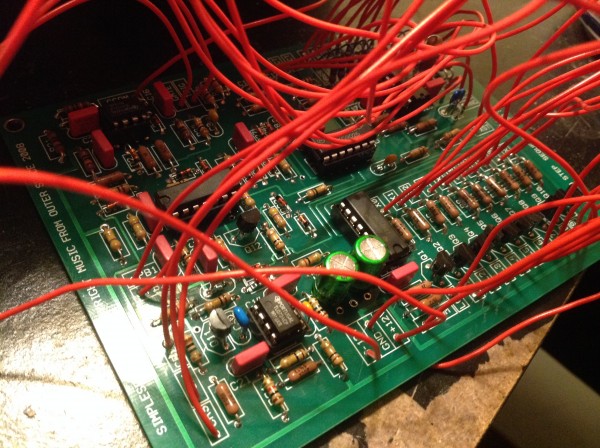
Alright pictures speak a thousand words I hope this will help....
Will post AC results ASAP..
But here are some pictures I hope will help trouble shoot this.
I also have a parts requisition list from Jameco and Mouser.
| Description: |
| This is what I am working with as far as tools go..... |
|
| Filesize: |
1.44 MB |
| Viewed: |
240 Time(s) |
| This image has been reduced to fit the page. Click on it to enlarge. |

|
| Description: |
| Wall Wart Dead at the moment.. |
|
| Filesize: |
1.35 MB |
| Viewed: |
230 Time(s) |
| This image has been reduced to fit the page. Click on it to enlarge. |

|
| Description: |
| What I'm using to power it currently |
|
| Filesize: |
1.57 MB |
| Viewed: |
223 Time(s) |
| This image has been reduced to fit the page. Click on it to enlarge. |

|
| Description: |
|
| Filesize: |
1.94 MB |
| Viewed: |
254 Time(s) |
| This image has been reduced to fit the page. Click on it to enlarge. |
|
| Description: |
|
| Filesize: |
1.98 MB |
| Viewed: |
217 Time(s) |
| This image has been reduced to fit the page. Click on it to enlarge. |

|
|
|
|
Back to top
|
|
|
Chartreuse-J
Joined: Jan 21, 2014
Posts: 8
Location: Dixie
|
| Posted: Wed Jan 22, 2014 7:46 pm Post subject:
|
|
|
The start stop feature to cycle through the gates is now intermittently working. Sometimes the unit just stays on the 1st gate and will not move to another gate, I think there might be a loose wire as I used solid core wire instead of stranded. Oh well..
Will post those AC results soon, as I might put this off until tomorrow. |
|
|
Back to top
|
|
|
elmegil
Joined: Mar 20, 2012
Posts: 2179
Location: Chicago
Audio files: 16
|
| Posted: Wed Jan 22, 2014 8:45 pm Post subject:
|
|
|
| Yeah, that sounds like grounding issues.... |
|
|
Back to top
|
|
|
Chartreuse-J
Joined: Jan 21, 2014
Posts: 8
Location: Dixie
|
| Posted: Thu Jul 03, 2014 2:13 pm Post subject:
|
|
|
As for the Sequencer
Was not grounding issues and still DOA.
As for the power supply.
I replaced the Diodes and the Caps and bought a new 3000mA 12v AC and junked the 500mA.
All caps/diodes were originally oriented correctly.... (so no fault there)
The problem was the high current from the BA Transformer fried the diodes.
So that was solved |
|
|
Back to top
|
|
|
|

 Forum index » DIY Hardware and Software » MusicFromOuterSpace.com designs by Ray Wilson
