| Author |
Message |
solaneu
Joined: Oct 21, 2014
Posts: 5
Location: suburban base
|
 Posted: Tue Oct 21, 2014 2:50 pm Post subject:
Yet another sequencer ((edit: answered) question) thread Posted: Tue Oct 21, 2014 2:50 pm Post subject:
Yet another sequencer ((edit: answered) question) thread
Subject description: this time with switches! |
  |
|
Howdy folks,
For the last few weeks I have been studying the forums for my sequencer project, which has been VERY helpful, and I thought I can ask a question since something has been bugging me lately and I couldn't find a solution for it. What I want is a sequencer that is switchable between 2x8 and 16 steps.
Right now I have 2 4017s for two 8 step sequences. I thought with a switch, I can route the clock first to a third 4017 with a two-step cycle. So first step of it would go to the clock input of first 4017 and second step to the clock input of second 4017. That way even though it jumps between two rows I have 16 steps. Same switch would also route the cv and gate outputs of second 4017 to first one so cv out1 and gate out1 recieve all 16 steps.
The problem is of course, two cv outputs overlap. That's why I thought I can add a SPDT switch that, with each clock signal changes its position, but from what I could see with most switches (4016, 4066) they rather respond if Enable is high or low and not the way I need, that is, switch when Enable is high and chillax and wait for the next clock when low.
So, I was wondering if it makes sense, if there is a way to do it or is there an easier way to do it?
Last edited by solaneu on Wed Oct 22, 2014 2:56 pm; edited 1 time in total |
|
|
Back to top
|
|
 |
PHOBoS

Joined: Jan 14, 2010
Posts: 5873
Location: Moon Base
Audio files: 709
|
| Posted: Tue Oct 21, 2014 3:56 pm Post subject:
|
|
|
 
Do you want the 2x8 to be in sync,. so just 8 steps but with 2 CV outputs, or do you want them to be completely seperate
so they can work at different speeds ?
it shouldn't be to hard to chain 2 4017's without the need for a third one if you use the CLK enable pins.
Have the first 4017 count to 9 steps, where the 9th steps disables the CLK of the first but resets the second 4017.
The second one then also counts 9 steps where the 9th steps disables its CLK and resets the first 4017. (and so on)
It's actually somewhat similar to what I did for the Euclidean Rhythm Generator.
_________________
"My perf, it's full of holes!"
http://phobos.000space.com/
SoundCloud BandCamp MixCloud Stickney Synthyards Captain Collider Twitch YouTube
Last edited by PHOBoS on Wed Oct 22, 2014 10:04 am; edited 1 time in total |
|
|
Back to top
|
|
|
solaneu
Joined: Oct 21, 2014
Posts: 5
Location: suburban base
|
| Posted: Wed Oct 22, 2014 8:56 am Post subject:
|
|
|
Hi PHOBoS,
They don't need to be completely in sync in 2x8 mode. I added 4040s before 4017 clock inputs so that their speeds may vary in relation to eachother. So 2 CV outputs and 2 Gate outputs in that mode.
I tried cascading the two 4017s the way its described in its data sheet and it works that way. I am not much of an electronics-savvy person but the logic behind it looks similiar to what you desribed. The problem with it is though, in cascaded mode, Q1 thru Q8 are the outputs, as in your schematic, but in 2x8 mode Q0 thru Q7 are the outputs. So it is kinda hard to make the sequencer switchable between 2x8 and 16 steps.
I also tried it with two 4015s, while it's easier to switch between 2x8 and 16 (with a DPDT switch), adjusting the sequence lengths with 4015s is just too complicated. |
|
|
Back to top
|
|
|
PHOBoS
Joined: Jan 14, 2010
Posts: 5873
Location: Moon Base
Audio files: 709
|
|
|
Back to top
|
|
|
solaneu
Joined: Oct 21, 2014
Posts: 5
Location: suburban base
|
| Posted: Wed Oct 22, 2014 11:45 am Post subject:
|
|
|
Just tried it out on breadboard and it works! I also clocked it externally and its stable at least at 600 bpm so no problems there either. Now it's time to figure out how to switch it.
Thanks PHOBoS! |
|
|
Back to top
|
|
|
PHOBoS
Joined: Jan 14, 2010
Posts: 5873
Location: Moon Base
Audio files: 709
|
|
|
Back to top
|
|
|
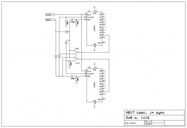
DUBmatze

Joined: Feb 18, 2013
Posts: 150
Location: south Germaica (schwabilon)
|
|
|
Back to top
|
|
|
PHOBoS
Joined: Jan 14, 2010
Posts: 5873
Location: Moon Base
Audio files: 709
|
|
|
Back to top
|
|
|
PHOBoS
Joined: Jan 14, 2010
Posts: 5873
Location: Moon Base
Audio files: 709
|
| Posted: Tue Jul 25, 2017 1:14 pm Post subject:
|
|
|
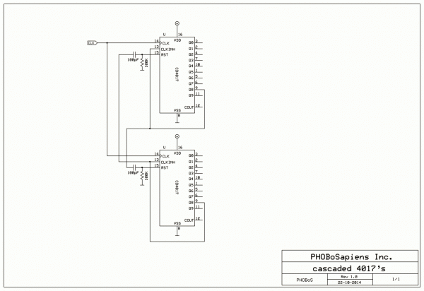
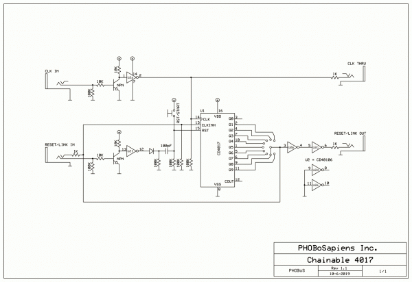
Dukester (who has yet to make an appearance on the forum) send me a message that he tested the switchable
version I posted and although the 1x16 mode worked the 2x8 mode skips step 1. I did a test myself and that is
indeed the case.
I think this actually makes sense if you look at the internal structure of the 4017. The CLK INH pin is internally
connected to an AND port (after being inverted) together with the CLK input. If you look at the circuit in 2x8 mode
then up untill the 8th step (Q7) it works fine. When Q8 goes high two things happen:
The CLK INH pin goes high which disables the CLK input but it also gets immediately reset. Because of this the CLK INH
pin goes low again. However because the CLK IN is still high this high to low transistion of the CLK INH pin creates a CLK
pulse through the internal AND gate. The result is that it skips step 1. I am slightly confused why it works fine in 1x16
mode.
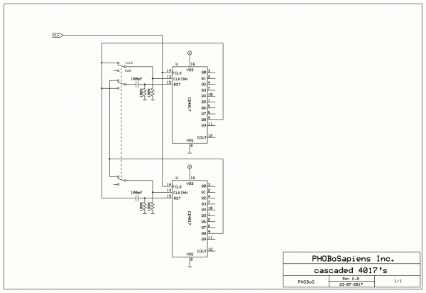
I did some tests to see if I could come up with a solution that wasn't too complex and I did manage to get something
working using a 3-pole switch (V2.0). It doesn't always work well when you switch to 1x16 mode though. Because I didn't
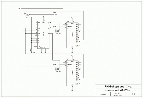
like the idea of using a 3-pole switch I tested if I could replace it with a mux so that only a single pole switch could be used
(V2.1). This worked and I managed to use the same switch to send a reset pulse to the first counter which makes the 1x16
mode work every time. Dukester has also tested this version and confirmed that it works. 
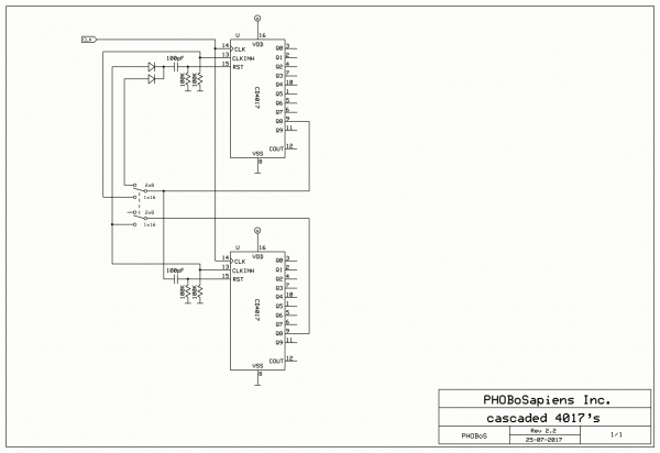
So I was going to post it (actually I am doing that now or I did when you read this) and I looked up the thread where I noticed
the schematic by DUBmatze. It doesn't work how it is drawn but I was curious what it would need to get it functioning. It first
got a bit more complex needing more diodes and a 3-pole switch but when I compared that to version I drew I noticed it could
be simplified. When I drew V2.0 I did had the suspicion that there was an easier way but just didn't see it, so thanks DUBmatze!
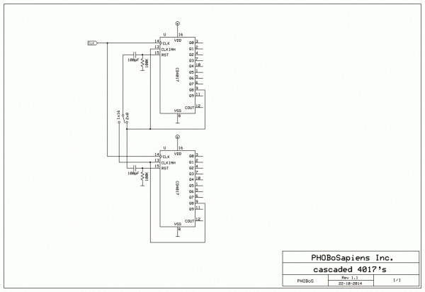
The end result is a version (V2.2) that needs a 2-pole switch and no mux and seems to work every time, at least it does on my
breadboard. (you could probably replace the switch with a mux).
Personally I would go for a different approach; 2 seperate sequencers that have individual CLK and reset inputs and a switch to
select the number of steps with an option to chain them. I think it would be possible to make it so you can chain more than 1.
I do recall drawing something like that once before so I will look into it or maybe come up with a new version.
| Description: |
| note: doesn't alway seem to work well when switching from 2x8 to 1x16 mode. |
|
| Filesize: |
44.51 KB |
| Viewed: |
836 Time(s) |
| This image has been reduced to fit the page. Click on it to enlarge. |
|
| Description: |
|
| Filesize: |
55.44 KB |
| Viewed: |
991 Time(s) |
| This image has been reduced to fit the page. Click on it to enlarge. |
|
| Description: |
|
| Filesize: |
45.05 KB |
| Viewed: |
1043 Time(s) |
| This image has been reduced to fit the page. Click on it to enlarge. |
|
_________________
"My perf, it's full of holes!"
http://phobos.000space.com/
SoundCloud BandCamp MixCloud Stickney Synthyards Captain Collider Twitch YouTube |
|
|
Back to top
|
|
|
Dukester
Joined: Jul 22, 2017
Posts: 1
Location: Ireland
|
| Posted: Tue Jul 25, 2017 4:29 pm Post subject:
|
|
|
I am here now, I made the account to message you about this haha 
I will have a go with that last design, see how i get on.
i would like to try a design in the future with more features but for now this works for me.
Cheers |
|
|
Back to top
|
|
|
Matthijn_Brink
Joined: Jun 04, 2019
Posts: 5
Location: Netherlands
|
| Posted: Sun Jun 09, 2019 3:09 pm Post subject:
|
|
|
| PHOBoS wrote: |
Personally I would go for a different approach; 2 seperate sequencers that have individual CLK and reset inputs and a switch to
select the number of steps with an option to chain them. I think it would be possible to make it so you can chain more than 1.
I do recall drawing something like that once before so I will look into it or maybe come up with a new version. |
I'm a 'bit' late to this thread, but I was wondering if you managed to figure this out eventually. It sounds like a really nice project. For now I'll try building your v2.2 design, thank you for posting it! |
|
|
Back to top
|
|
|
PHOBoS
Joined: Jan 14, 2010
Posts: 5873
Location: Moon Base
Audio files: 709
|
|
|
Back to top
|
|
|
PHOBoS
Joined: Jan 14, 2010
Posts: 5873
Location: Moon Base
Audio files: 709
|
|
|
Back to top
|
|
|
PHOBoS
Joined: Jan 14, 2010
Posts: 5873
Location: Moon Base
Audio files: 709
|
|
|
Back to top
|
|
|
Matthijn_Brink
Joined: Jun 04, 2019
Posts: 5
Location: Netherlands
|
| Posted: Mon Jun 10, 2019 12:56 pm Post subject:
|
|
|
Thank you so much for the reply
After my exams are done I'll be attempting to to piece this together, really hyped for it. |
|
|
Back to top
|
|
|
Matthijn_Brink
Joined: Jun 04, 2019
Posts: 5
Location: Netherlands
|
| Posted: Wed Jun 12, 2019 9:35 am Post subject:
|
|
|
| PHOBoS wrote: | Here's a version with some buffers and protection and a reset switch.
You could use the spare inverters to make an oscillator for the clock. |
I tried to simulate this one in MultiSim, but I can't quite figure out how to link the two. By just connecting the reset links I only ended up with the two chips running in sync...
Is there some obvious thing I'm missing that I should be connecting/disconnecting?
Thanks in advance! |
|
|
Back to top
|
|
|
PHOBoS
Joined: Jan 14, 2010
Posts: 5873
Location: Moon Base
Audio files: 709
|
| Posted: Wed Jun 12, 2019 12:57 pm Post subject:
|
|
|
Let's see. You need an oscillator connected to the CLK IN and connect the CLK THRU to the CLK IN of the next one, you probably did that part ok.
LINK OUT of the first one needs to be connected to the LINK IN of the second one and the LINK OUT of that connected to the LINK IN of the first one.
You probably did that right too, but,..
you see that 1K resistor on the LINK IN (connected to pin 13), leave it out so you only connect to the 100K/10K resistors. If you use a connector with
a switch contact this connection will be broken automatically when you plug something in. With nothing plugged in it will never stop running.
So if you simulate a single one without that connection it should only run once and than stop at the 'last' step (whatever you select).
For simulating you could also test the other version I posted (with the switch) as it should work exactly the same.
Although I haven't tested the circuit as drawn I did patch up something similar and that worked fine.
_________________
"My perf, it's full of holes!"
http://phobos.000space.com/
SoundCloud BandCamp MixCloud Stickney Synthyards Captain Collider Twitch YouTube |
|
|
Back to top
|
|
|
Matthijn_Brink
Joined: Jun 04, 2019
Posts: 5
Location: Netherlands
|
| Posted: Sun Jun 16, 2019 12:00 pm Post subject:
|
|
|
| Thanks, I can't seem to figure it out in Multisim, so I'll just have to wait until my breadboard comes in :b |
|
|
Back to top
|
|
|
Matthijn_Brink
Joined: Jun 04, 2019
Posts: 5
Location: Netherlands
|
| Posted: Sun Jun 16, 2019 12:26 pm Post subject:
|
|
|
| Okay so I got the one with the switch kind of working. Am I correct in thinking that Q9 (pin 11) should not be connected to an LED or pot? Because right now pin 11 stays high until the other chip has reached its pin 11 and resets the chip again. (This is without a step selector, just running both chips from Q1-Q9). |
|
|
Back to top
|
|
|
PHOBoS
Joined: Jan 14, 2010
Posts: 5873
Location: Moon Base
Audio files: 709
|
|
|
Back to top
|
|
|
maltasynth65
Joined: Jul 20, 2016
Posts: 10
Location: MALTA
|
| Posted: Fri May 29, 2020 9:13 pm Post subject:
seq step selector option |
|
|
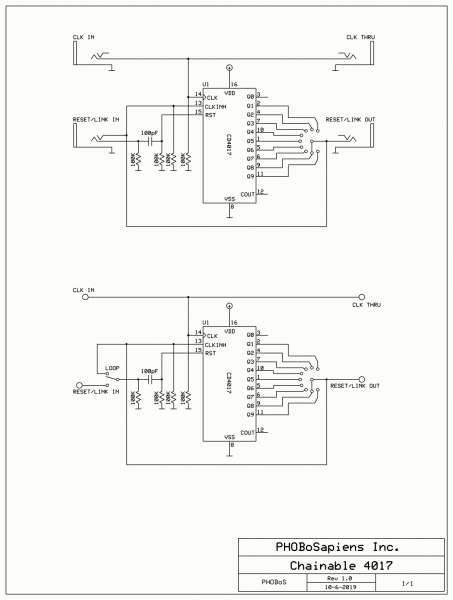
| PHOBoS wrote: | This is what I had in mind for cascading (not tested) which uses outputs Q0-Q7 on both 4017's.
I do have another idea without capacitors involving AND gates (different from the datasheet) and if that works
you should be able to run it faster, but I'd really need to test that first.
This one should work well into (and probably beyond) the audiorange though. |
this refers to the post posted by PHOBoS on 22 oct 2014 10:26 with drawing CASCADED 4017'S ver. 1.0
I have built this as a stand-alone 16 step seq and can confirm that this works, but i am struggling to add to it a variable step count before reset. My idea is to use a 12-way selector switch to get anything from 1-4 and 1-16 step sequence. Any help would be appreciated. Thanks |
|
|
Back to top
|
|
|
Lysol
Joined: Mar 06, 2012
Posts: 12
Location: PA
|
| Posted: Wed Jul 29, 2020 8:59 pm Post subject:
|
|
|
| PHOBoS wrote: | This is what I had in mind for cascading (not tested) which uses outputs Q0-Q7 on both 4017's.
I do have another idea without capacitors involving AND gates (different from the datasheet) and if that works
you should be able to run it faster, but I'd really need to test that first.
This one should work well into (and probably beyond) the audiorange though. |

I have this breadboarded and it works! What I'd like to do now is figure out how to add in toggle switches to select the amount of steps in a sequence.
I was under the impression that it would just be a matter of connecting the output of a given step to the reset pin, but this does not appear to be working (or at least to any degree of predictability).
It sometimes works if the sequence has not advanced to the 2nd IC yet (ex. cycling through steps #1-4), but also sometimes doesn't (the sequence will just fully stop - no step outputs at all - and have to be reset.
If it has advanced to the 2nd IC (if I would want to have it cycle, for example, steps 1-12) then all sorts of unpredictable things may happen: again, it may just completely stop, or a step may be skipped and then both 4017s are counting in sync, etc
Is there a way to use this schem and have this functionality? |
|
|
Back to top
|
|
|
PHOBoS
Joined: Jan 14, 2010
Posts: 5873
Location: Moon Base
Audio files: 709
|
| Posted: Thu Jul 30, 2020 7:59 am Post subject:
|
|
|
| Lysol wrote: | | PHOBoS wrote: | This is what I had in mind for cascading (not tested) which uses outputs Q0-Q7 on both 4017's.
I do have another idea without capacitors involving AND gates (different from the datasheet) and if that works
you should be able to run it faster, but I'd really need to test that first.
This one should work well into (and probably beyond) the audiorange though. |
I have this breadboarded and it works! What I'd like to do now is figure out how to add in toggle switches to select the amount of steps in a sequence.
I was under the impression that it would just be a matter of connecting the output of a given step to the reset pin, but this does not appear to be working (or at least to any degree of predictability).
It sometimes works if the sequence has not advanced to the 2nd IC yet (ex. cycling through steps #1-4), but also sometimes doesn't (the sequence will just fully stop - no step outputs at all - and have to be reset.
If it has advanced to the 2nd IC (if I would want to have it cycle, for example, steps 1-12) then all sorts of unpredictable things may happen: again, it may just completely stop, or a step may be skipped and then both 4017s are counting in sync, etc
Is there a way to use this schem and have this functionality? |
it should be possible to adjust the amount of steps by using the connection to Q8 and connecting it to another output. This could cause some initial weirdness
but it should work after 1 or 2 cycles. There is indeed a chance of it latching up which is also possible with the orginal circuit. And no, using the reset pin like
you usually see doesn't work for this. If you look at the first 4017 it counts through the steps untill Q8 becomes high (this step is not used as an output btw).
When that happens it disables its own CLK input by making the CLKINH pin high so it just stops counting untill it gets reset. The second 4017 works the same
way but there is a cross coupling between the 2 so when one halts the other gets reset and vice versa.
The chainable version is basically the same but with a switch to select the number of steps. You could use toggle switches, which I personally find to work much
nicer than a rotary switch, but you do need to add some diodes to prevent shorting outputs together. The 'Little Gate' Sequencer might help you out with that.
_________________
"My perf, it's full of holes!"
http://phobos.000space.com/
SoundCloud BandCamp MixCloud Stickney Synthyards Captain Collider Twitch YouTube |
|
|
Back to top
|
|
|
Lysol
Joined: Mar 06, 2012
Posts: 12
Location: PA
|
| Posted: Thu Jul 30, 2020 8:54 am Post subject:
|
|
|
| PHOBoS wrote: | | Lysol wrote: | | PHOBoS wrote: | This is what I had in mind for cascading (not tested) which uses outputs Q0-Q7 on both 4017's.
I do have another idea without capacitors involving AND gates (different from the datasheet) and if that works
you should be able to run it faster, but I'd really need to test that first.
This one should work well into (and probably beyond) the audiorange though. |
I have this breadboarded and it works! What I'd like to do now is figure out how to add in toggle switches to select the amount of steps in a sequence.
I was under the impression that it would just be a matter of connecting the output of a given step to the reset pin, but this does not appear to be working (or at least to any degree of predictability).
It sometimes works if the sequence has not advanced to the 2nd IC yet (ex. cycling through steps #1-4), but also sometimes doesn't (the sequence will just fully stop - no step outputs at all - and have to be reset.
If it has advanced to the 2nd IC (if I would want to have it cycle, for example, steps 1-12) then all sorts of unpredictable things may happen: again, it may just completely stop, or a step may be skipped and then both 4017s are counting in sync, etc
Is there a way to use this schem and have this functionality? |
it should be possible to adjust the amount of steps by using the connection to Q8 and connecting it to another output. This could cause some initial weirdness
but it should work after 1 or 2 cycles. There is indeed a chance of it latching up which is also possible with the orginal circuit. And no, using the reset pin like
you usually see doesn't work for this. If you look at the first 4017 it counts through the steps untill Q8 becomes high (this step is not used as an output btw).
When that happens it disables its own CLK input by making the CLKINH pin high so it just stops counting untill it gets reset. The second 4017 works the same
way but there is a cross coupling between the 2 so when one halts the other gets reset and vice versa.
The chainable version is basically the same but with a switch to select the number of steps. You could use toggle switches, which I personally find to work much
nicer than a rotary switch, but you do need to add some diodes to prevent shorting outputs together. The 'Little Gate' Sequencer might help you out with that. |
Yes, I am interested in wiring in center off toggles like in the "Little Gate" sequencer for "STEP ON" - "OFF" - "RESET" for each step!
So for the schem I used (the first one your posted in the thread) are you saying that connecting steps to Q8 for resetting should work? Apologies if I am not fully understanding.
Is there a way to cascade the "little gate" sequencer to an additional 4017 to get 16 steps?
Or, to get the functionality that I want would it be more wise to just attempt cascading them as outlined in fig. 19 in the manual? (via an AND gate?).
Much appreciated! |
|
|
Back to top
|
|
|
PHOBoS
Joined: Jan 14, 2010
Posts: 5873
Location: Moon Base
Audio files: 709
|
| Posted: Sat Aug 01, 2020 12:01 pm Post subject:
|
|
|
| Quote: | | So for the schem I used (the first one your posted in the thread) are you saying that connecting steps to Q8 for resetting should work? Apologies if I am not fully understanding. |
No, you need to change the connection from Q8 to any of the other ouputs. So instead of connecting the ouputs to the reset pin
as you would normally do (with a single 4017) you have to connect it to the CLKINH pin and (through a capacitor) to the reset pin of the other 4017.
You will end up with 2 sets of toggle switches, one set for each 4017 so if for example you want 12 steps, you could set both to 6 steps, or one to 7
and the other to 5 steps or any combination that results in a total of 12.
HOWEVER: It will do some weird stuff when you change the step length and a much better solution for more steps would be to use a binary counter
(4040, 4029, 4520) and a binary to decimal decoder (4514) or a mux (4067) instead of 2 4017s.
| Quote: | | Or, to get the functionality that I want would it be more wise to just attempt cascading them as outlined in fig. 19 in the manual? (via an AND gate?). |
Although the version in the datasheet is different it works somewhat similar and I don't think it would be muich of an improvement.
_________________
"My perf, it's full of holes!"
http://phobos.000space.com/
SoundCloud BandCamp MixCloud Stickney Synthyards Captain Collider Twitch YouTube |
|
|
Back to top
|
|
|
|

 Forum index » DIY Hardware and Software » Lunettas - circuits inspired by Stanley Lunetta