| Author |
Message |
bloodniece

Joined: Jun 20, 2005
Posts: 11
Location: Nashville
Audio files: 1
|
 Posted: Mon Jun 20, 2005 2:15 pm Post subject:
External Trigger with Piezos Posted: Mon Jun 20, 2005 2:15 pm Post subject:
External Trigger with Piezos |
  |
|
Hi,
I'm new to the list and am diggin' the tips and ideas. I want to trigger the SoundLab externally via piezos as a drum trigger. Ray has a schematic for audio signal to gate. Would this work for piezos? I want to avoid building something I can't use. (well, it does sound like fun to play guitar to trigger the gate)
Thanks
Derek
See photos of my Sound Lab here --> http://www.tanasfuck.com/soundlab/ |
|
|
Back to top
|
|
 |
Afro88

Joined: Jun 20, 2004
Posts: 701
Location: Brisbane, Australia
Audio files: 12
G2 patch files: 79
|
| Posted: Mon Jun 20, 2005 4:37 pm Post subject:
|
|
|
Haha, nice design!  Love the knobs, and the palm tree near the mixer is a nice touch Love the knobs, and the palm tree near the mixer is a nice touch 
Sorry, I can't help with the piezo triggers... |
|
|
Back to top
|
|
|
bloodniece
Joined: Jun 20, 2005
Posts: 11
Location: Nashville
Audio files: 1
|
| Posted: Mon Jun 20, 2005 7:15 pm Post subject:
|
|
|
thanks.
i might build the audio to trigger anyway. I imagine it'll work for piezos just fine. |
|
|
Back to top
|
|
|
mosc
Site Admin

Joined: Jan 31, 2003
Posts: 18198
Location: Durham, NC
Audio files: 213
G2 patch files: 60
|
| Posted: Mon Jun 20, 2005 7:41 pm Post subject:
|
|
|
 Great to have you here. Great to have you here.
The pictures of your Sound Lab are great. I love the look you have achieved. Very nice.
There are some good topics here with links to great piezo resources here on the forum. Try the search feature.
_________________
--Howard
my music and other stuff |
|
|
Back to top
|
|
|
opg

Joined: Mar 29, 2004
Posts: 954
Location: Berkeley, CA, US
Audio files: 3
|
| Posted: Tue Jun 21, 2005 5:54 am Post subject:
|
|
|
Sounds a little like the drum trigger module my friend is building- which should be done this week! There will be plenty of pictures and possibly source code/schematics.
-8 inputs for acoustic drum triggers
-No annoying factory preset sounds
-Load and assign your own sounds, just like a sampler
-Force sensitive
-No MIDI
-Currently set up for 8-bit sounds, but 16-bit 44100 sounds may be possible in the future |
|
|
Back to top
|
|
|
bloodniece
Joined: Jun 20, 2005
Posts: 11
Location: Nashville
Audio files: 1
|
| Posted: Tue Jun 21, 2005 4:59 pm Post subject:
|
|
|
| Keep us posted on that project. sounds def. |
|
|
Back to top
|
|
|
bloodniece
Joined: Jun 20, 2005
Posts: 11
Location: Nashville
Audio files: 1
|
| Posted: Tue Jun 21, 2005 5:04 pm Post subject:
|
|
|
| mosc wrote: | Great to have you here.
The pictures of your Sound Lab are great. I love the look you have achieved. Very nice.
There are some good topics here with links to great piezo resources here on the forum. Try the search feature. |
Thanks, I'll search away. I'm working on getting a PCB layout for the Audio Signal to Gate circuit. Anyone every used Osmond Quartz for PCB design? |
|
|
Back to top
|
|
|
Mike Walters

Joined: Mar 24, 2005
Posts: 29
Location: Chapel Hill NC
|
| Posted: Tue Jun 21, 2005 8:14 pm Post subject:
|
|
|
Maybe the piezo could activate the v-trig input? That's a transistor that just switches the manual gate (I believe). The voltage from the piezo to the base pin might be enough to cause the transistor to switch??
_________________
-Mike Walters
www.mysterycircuits.com |
|
|
Back to top
|
|
|
bloodniece
Joined: Jun 20, 2005
Posts: 11
Location: Nashville
Audio files: 1
|
| Posted: Tue Jun 21, 2005 9:30 pm Post subject:
Piezos redux |
|
|
I tried to no avail with a commercial piezo trigger robbed from a drum set.
Perhaps not enough voltage to make the tranny to switch? As soon as I finish the board layout for the audio signal to gate I'll post it here and with Ray at musicfromouterspace |
|
|
Back to top
|
|
|
jksuperstar

Joined: Aug 20, 2004
Posts: 2503
Location: Denver
Audio files: 1
G2 patch files: 18
|
| Posted: Tue Jun 21, 2005 10:22 pm Post subject:
|
|
|
| The current out of a piezo is extrememly small, you might want to through it through a buffer (like an LM324 or any other generic op-amp). You can hang a cap & resistor on it also, if the pulse out of the piezo is to short for a reliable trigger. Google the PAIA website, and search there for the thumb drum schematics...they should help. |
|
|
Back to top
|
|
|
opg
Joined: Mar 29, 2004
Posts: 954
Location: Berkeley, CA, US
Audio files: 3
|
| Posted: Fri Jul 08, 2005 10:32 am Post subject:
|
|
|
| jksuperstar wrote: | | The current out of a piezo is extrememly small, you might want to through it through a buffer (like an LM324 or any other generic op-amp). You can hang a cap & resistor on it also, if the pulse out of the piezo is to short for a reliable trigger. Google the PAIA website, and search there for the thumb drum schematics...they should help. |
This is very true. You really need to amplify the signal from a piezo trigger. Why, I once took a cheap Radio Shack piezo transducer and a 1/4" jack and plugged it into a mixer. I could could only hear anything if the gain and volume was way up.
I can check to see what went into the drum module... |
|
|
Back to top
|
|
|
adhdboy
Joined: Feb 16, 2005
Posts: 57
Location: denver
|
|
|
Back to top
|
|
|
adhdboy
Joined: Feb 16, 2005
Posts: 57
Location: denver
|
|
|
Back to top
|
|
|
Wild Zebra

Joined: Apr 28, 2005
Posts: 806
Location: Ohio
Audio files: 5
|
| Posted: Mon Jul 11, 2005 7:36 am Post subject:
|
|
|
Thanks thats pretty darn cool.
_________________
"your stripes are killer bro" |
|
|
Back to top
|
|
|
Macaba
Joined: Jul 13, 2005
Posts: 160
Location: UK
|
| Posted: Sun Jul 17, 2005 1:45 pm Post subject:
|
|
|
| I was wondering, seeing as I have TL084's around here, if i could use that as the op-amp in the drum circuit? |
|
|
Back to top
|
|
|
adhdboy
Joined: Feb 16, 2005
Posts: 57
Location: denver
|
| Posted: Sun Jul 17, 2005 2:49 pm Post subject:
|
|
|
Sure they should work fine. The LF444 is just the standard op amp I breadboard with. Its just a low current version of a quad JFET op amp.
_________________
There 10 kinds of people in this world that understand binary those that do and those that don't. |
|
|
Back to top
|
|
|
Macaba
Joined: Jul 13, 2005
Posts: 160
Location: UK
|
| Posted: Mon Jul 18, 2005 1:54 am Post subject:
|
|
|
Thanks alot.
I'm starting AS level electronics this september, so by this time next year, hopefully i'll be designing my own synth circuits!  |
|
|
Back to top
|
|
|
v-un-v
Janitor


Joined: May 16, 2005
Posts: 8933
Location: Birmingham, England, UK
Audio files: 11
G2 patch files: 1
|
| Posted: Mon Jul 18, 2005 2:41 am Post subject:
|
|
|
| Macaba wrote: | | I'm starting AS level electronics this september, so by this time next year, hopefully i'll be designing my own synth circuits! :) |
Well lets hope the extremely stale and dry lecturers don't dash your dreams to quickly ;) When I studied electronics- the teachers didn't know what to make of me, and especially didn't know what to make of electronic music.
An old friend of mine from Bristol had a really good time and his main tutor was very sympathetic. So I suppose it's luck of the draw.
best of luck anyhow :) I too am hoping to start a degree in 3D product design and Computer-aided product design in September- as a mature student- looks like a lot of fun :) |
|
|
Back to top
|
|
|
Macaba
Joined: Jul 13, 2005
Posts: 160
Location: UK
|
| Posted: Thu Jul 21, 2005 5:48 am Post subject:
|
|
|
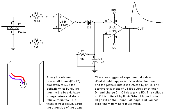
I have just breadboarded the final circuit on ray's page:
http://www.musicfromouterspace.com/analogsynth/SOUNDLABMINISYNTH/drum_trigger.html
And I'm so pleased! This is the first time a breadboard successfully worked first time, and so well too! (It is simple enough!).
Its beautiful! On my VCO, if I plug the cv into the exponental CV, then I can have any pitch dependant on strike impact, if i plug into the linear CV, i get a much more controlled impact change, you actually have to manual adjust the VCO to a start pitch and the piezo makes it jump slightly, a cool sound.
I want to learn about OP amps, and this circuit looks like a good example, so i'm gonna go though how i think it works and someone knowledgable can correct me.
1. The resistors accross the piezo are to reduce the voltage from hundreds of volts to something more managable.
2. The first op-amp simply amplifies the current as much as it can. (Not sure of the gain on the TL084 i used, anyone know?)
3. D1 is to stop C1 from discharging in the wrong direction.
4. The R5 and C1 combo is to provide a Release ramp, so to speak.
5. Then op amp B is to amplify this signal again.
6. Going to the trigger section, R7 and C2 is to make the pulse last a minimum interval so that the trigger can be detected by the circuitry in a synth? - This is a bit iffy, not sure about this.
7. Op amp C amplifies again (why all this amplification?)
8. Not sure why C3 and R8 are there.
9. The 2 resistor and cap arrangment attached to pin 13 is to only switch on the OP amp for a slight amount of time to make a proper trigger pulse?
EDIT: I've just read ray's description more carefully. Seems i'm wrong on most counts.
Thanks for anyone who helps. |
|
|
Back to top
|
|
|
|

 Forum index » DIY Hardware and Software » MusicFromOuterSpace.com designs by Ray Wilson